Meet Powerline Emissions and Immunity Standards or Else: A Guide to Verifying Test Systems
Download this article in PDF format.
There’s no escaping it—all electrical products sold in Europe, China, Japan, Korea, Brazil, and many other countries must meet IEC standards that specify maximum permitted emissions, as well as immunity requirements. In Europe, the IEC standards are accompanied by equivalent EN versions, and China, Japan, etc. have their own National Standards versions. An example is IEC 61000-3-2: EN 61000-3-2 is the equivalent that has the force of law in Europe, JIS C 61000-3-2 is applicable in Japan, and in China it’s known as GB/T 14549-93 and issued by the Standards Administration of China Technical Committee 246 (SAC/TC246).
Systems to test electrical products against emissions and immunity systems are available from several vendors. Fully integrated systems are usually type tested by the manufacturer, while key building blocks, such as power analyzers and programmable power sources, have also been verified by their respective manufacturers.
These systems need to be calibrated and verified periodically to assure that they still operate accurately. Also, when hardware, software, or firmware upgrades are installed, it’s often necessary to verify correct operation, especially for accredited test facilities. In recent years, several calibration and verification protocols have been published, such as IEC TR 61000-4-37 (harmonics) and IEC TR 61000-4-38 (flicker). This article deals with procedures and methods that can be used for on-site system verification and calibration, and are suitable for test laboratory accreditation purposes.
Emission Standards and System Verification
The IEC standards that apply to harmonic current emissions are IEC 61000-3-2 for products up to 16 A (per phase) and IEC 61000-3-12 for products up to 75 A per phase. IEC 61000-3-3 and IEC 61000-3-11 limit voltage fluctuations and flicker for products up to 16 A and 75 A, respectively. Harmonic measurement procedures and methods are specified in IEC 61000-4-7, and voltage fluctuation/flicker measurement methods are specified in IEC 61000-4-15. A typical harmonics and flicker test system configuration is illustrated in Figure 1.
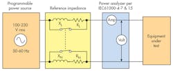
The main components are a programmable power source, one or more impedance units, a power analyzer, and, of course, the equipment under test (EUT) that is powered and measured. In some cases, additional instruments—or instrument options—to perform immunity testing per IEC 61000-4-11 and IEC 61000-4-13 are part of the system, but we will review these in more detail in the next section of this article. Several national laboratories have developed calibration methods and procedures to calibrate power analyzers.
A perfectly calibrated power analyzer is no guarantee, however, that the harmonic analysis and/or flicker tests will conform to the standards. The (programmable) power source and (reference) impedance units can also affect system accuracy, and in some cases, the system wiring and/or integration can cause problems.
For example, a power source with excessive output impedance (inductance) can affect both harmonics and flicker measurements. An incorrect impedance unit can affect flicker testing. There have been cases where the system wiring caused problems, with the neutral being grounded on the power source, as well as on the equipment being tested, thus bypassing the neutral part of the Reference Impedance. In other instances, the power source controlled the voltage adequately for slowly changing loads, but could not handle sudden load changes, i.e., over-stating voltage fluctuations and flicker.
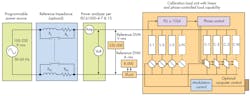
IEC TR 61000-4-37 describes methods to test the whole system and verify that harmonic current testing accuracy meets the requirements of IEC 61000-4-7 and IEC 61000-3-2/12. IEC TR 61000-4-38 describes methods to verify complete flicker test systems. In both cases, a precisely controlled load unit simulates real electrical products. In other words, the power source has to supply clean and distortion-free power to the controlled load. And the load can produce harmonics and flicker just like real products. Thus, there’s current flow through the impedance as with real products (Fig. 2).
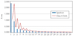
With the approach shown in Fig. 2, a variety of EUTs can be simulated. Therefore, it’s possible to verify that the test system functions properly for this variety of actual electrical equipment. For example, the waveform pattern in Fig. 3 emulates a product that has current emissions that PASS the limits of Class-A per IEC 61000-3-2.
Harmonic Current Testing per IEC 61000-3-2 and IEC 61000-3-12
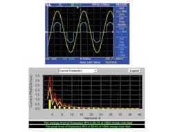
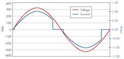
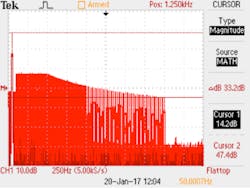
As the oscilloscope shot in Fig. 3 illustrates, the phase controlled load (C1-C4) can be turned on/off at user-selected points. Controlling the current flow through a precisely known resistive load produces an exactly determined harmonic spectrum. For example, turning an 80-Ω load “on” at 45 degrees and “off” at 135 degrees—much like in Fig. 3—produces the spectrum and harmonic values as shown in Fig. 4.
It’s easy to compute permitted tolerances, such as the 5 % permitted by IEC 61000-4-7. Alternatively, clause 6.2.3.2 of IEC 61000-3-2 specifies a reproducibility of ±(1% + 10 mA) that applies when the same equipment is tested on different systems. If we consider the calibration load in Fig. 2 to be that “same equipment,” we can use clause 6.2.3.2, but adopt a tolerance that’s more stringent than that clause for the verification of a harmonic test system.
For example, a tolerance of ±(0.3% + 5 mA) provides a margin of about 3:1, enough to confidently verify and certify the system, provided the system meets those tighter tolerances. Various patterns can be used to test individual test classes of IEC61000-3-2/12. Fig. 5 shows a Class-C “just pass” pattern, with harmonics up to 99.2 % of the limit.
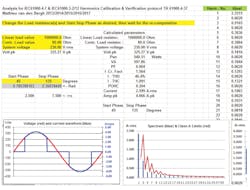
For IEC 61000-4-37, a supporting spreadsheet can be downloaded, which permits the user to calculate harmonics for any pattern that’s desired, and set this pattern with the calibration load. IEC 61000-4-37 specifies 12 different patterns, with increasing degrees of difficulty, but the user may select custom patterns as well.
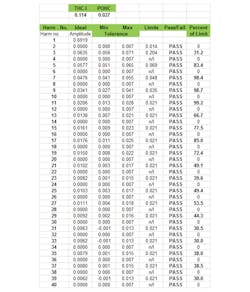
Fig. 6 illustrates a partial snapshot of the support spreadsheet. The user enters the load that’s applied, selects the start/stop phase angles (for the current conduction), and the spreadsheet implements a Fourier transform and computes the (ideal) expected harmonics with 0.1-mA resolution and accuracy. Thus, one sets the calibration load to a specific load level and start/stop phase for the current flow, runs the harmonics test system, and subsequently compares the system’s test report against the expected harmonics, power, total harmonics distortion (THD), total harmonic current (THC), and partial odd harmonic current (POHC) levels. IEC TR 61000-4-37 provides guidance for the specified patterns.
Flicker Testing per IEC 61000-3-3 and IEC 61000-3-11
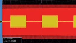
A similar approach as just discussed applies to flicker-test-system verification in accordance with IEC 61000-3-3/11, and per IEC TR 61000-4-38. By turning a known load “on” and “off,” one can produce a precisely known test pattern, as the current flow through the Reference Impedance produces an exactly known voltage drop. For example, modulating the load at 8.77 Hz produces a pattern as shown in Fig. 7.
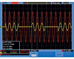
The yellow trace represents the current flow, which is turned “on” for 57 ms, then turned “off” for 57 ms, i.e., at a rate of 8.77 Hz. The known load resistance allows the user to precisely calculate the voltage drop through the IEC TR 60725-compliant Reference Impedance, and thus permits the flicker test system to be verified and calibrated. By measuring the generated voltage, one can also verify that the power source plus Reference Impedance are correctly configured. In other words, the system components can be adjusted if required.
In a number of cases, adjustments proved to be necessary. When the Reference Impedance is exactly per the IEC TR 60725 technical report, having a total impedance of (0.400 Ω + j 0.250 Ω) the total impedance from source to impedance output is often too high, as the source plus wiring contribute perhaps as much as 25–40 mΩ, and maybe 100 µH, thus causing errors up to 10%!!
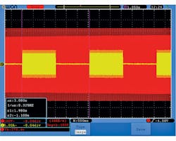
This type of system problem isn’t detected when one just calibrates the power analyzer, and verifies the impedance unit to be accurate. It’s ONLY detected when applying a real load, just like a real EUT represents. It’s easy to verify modulation timing (Figs. 7 and 8). Knowing the load (and thus the current level), and verifying the timing, one can produce patterns that meet the requirements of the calibration points in Table 5 of IEC 61000-4-15
Powerline Immunity Testing per IEC61000-4-11 and IEC 61000-4-13
The two most common immunity test standards are IEC 61000-4-11 for voltage dips and interrupts, and IEC 61000-4-13 for harmonic and inter-harmonic disturbances, both on the public supply voltage. Voltage dips and interrupts of the public supply are rather common. They’re due to heavy loads (motors or big electrical systems) starting up, short circuits at the residence or neighborhood level, switching of distribution equipment, etc.
Harmonic and/or inter-harmonic disturbances are present on the public supply all of the time, and may be caused by the aggregate effect of consumer electronic equipment, industrial controls, etc. Because these disturbances can be present at any time, electrical equipment must be able to “survive” the disturbances in a controlled fashion.
The EUT can either “ride through” the dips and interrupts, or specify an “orderly” recovery process, being either automatic or requiring manual intervention. Fig. 9 shows an example of a 1-cycle drop-out, and a dip to 40% for 10 cycles.
IEC 61000-4-11 specifies that the dips and interrupt generator are tested with a 100-Ω resistive load. The load unit shown in Fig. 2 can be used as an appropriate load for the tests. Although the IEC 61000-4-11 standard is being reviewed at this time, and may change, the existing version requires that voltage changes are made within 1 to 5 µs when tested with a 100-Ω load. For changes that start/stop at the voltage zero crossing, rise/fall times are meaningless, so the transition times are usually checked at 90 or 270 degrees. Fig. 10 illustrates this fast fall time—at 90º—from 230 V/50 Hz (325 V pk) to “0” V and the rise time—at 90º—as the voltage returns one cycle later.
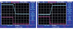
Thus, compliance with IEC 61000-4-11 can be verified by running the preferred test levels per Table 1 of the standard, measuring levels and timing with a good digital oscilloscope, and using a 100-Ω load.
Disturbances per IEC 61000-4-13 are a little more complicated to verify. The standard specifies a series of harmonic and inter-harmonic distortion patterns that are commonly found on the public supply voltage. Harmonic distortion is present virtually all of the time, and varies from 1% to 2% during very light load (night) conditions, to as much as 5% (or even more) during peak demand period.
In Europe, EN 50160 specifies the power quality that utilities have to meet. Distortion has to be less than 5% for 95% of the time, and can’t exceed 8% at any time. Other world regions either have formal laws governing power quality as well, or have generally accepted specifications in place (such as IEEE-STD 519 in the U.S.). So, since distortion can be present all of the time, electrical equipment must be able to handle these conditions.
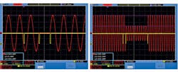
The 61000-4-13 standard, much like IEC 61000-4-11, has various test classes, with Class-2 applying for most equipment. The standard specifies harmonic and inter-harmonic tests, and the so-called Meister Curve (Fig. 11). The Meister Curve, in essence, simulates “ripple control” signals that the utility may superimpose on the public supply to control distribution equipment, and to switch electricity metering from day to night tariff. The ripple control signals can easily have 5% amplitude at inter-harmonic frequencies. The utilities normally avoid (integer) harmonic frequencies, as harmonics can be present all ofthe time, and could thus accidentally switch distribution gear.
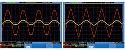
Fig. 12 shows the “flat top” harmonic disturbance pattern, usually caused by single-phase (consumer) electric equipment and the “over-swing” distortion pattern, which is typically caused by three-phase equipment in (light) industrial environments.
Summary
Compliance test systems can be verified, such as for certification purposes, at the user’s premises with a suitable load unit, along with good-accuracy digital multimeters, current shunts, and digital oscilloscopes with sufficient memory and timing accuracy.
IEC Technical Report 61000-4-37 provides guidance for the verification and calibration of harmonics emission test systems in accordance with IEC standards 61000-3-2 and 61000-3-12. IEC Technical Report 61000-4-38 offers guidance for verifying and calibrating voltage-fluctuation and flicker test systems in accordance with IEC standards 61000-3-3 and 61000-3-11.
Testing to IEC 61000-4-11 and IEC 61000-4-13 can be accomplished by using a suitable load, DVMs, and digital oscilloscopes having sufficient memory and resolution. The preferred test tables in both standards provide guidance for the most common test patterns.
Mathieu van den Bergh has participated in IEC standard efforts since 1996, and is a member of IEC/TC77A/WG-1-WG2-WG6, and the UL-STP 1741. He has written numerous articles concerning test-and-measurement instrumentation that have been published in the U.S., Europe, and Asia. He received the John M. Fluke Memorial Award for his work in creating the VXI standard. He has specialized in power-related harmonics and flicker applications for over 20 years. Mathieu van den Bergh can be reached at CNS-Poway at (858-486-4707) or via [email protected].
References
IEC 61000-3-2 Limits for harmonic current emissions for equipment ≤ 16 A /phase
IEC 61000-3-3 Limitation of voltage changes, fluctuations, and flicker for equipment ≤ 16A /phase
IEC 61000-3-11 Limitation of voltage changes, fluctuations, and flicker for equipment ≤ 75A /phase
IEC 61000-3-12 Limits for harmonic current emissions for equipment ≤ 75 A /phase
IEC 61000-4-7 General guidelines for harmonic and inter-harmonic measurements
IEC 61000-4-15 Flickermeter, functional and design specifications
IEC 61000-4-11 Voltage dips, short interruptions and voltage variations immunity tests
IEC 61000-4-13 Harmonics and inter-harmonics including mains signaling immunity test
IEC TR 61000-4-37 Calibration and verification protocol for harmonic emission compliance test systems
IEC TR 61000-4-38 Test, verification and calibration protocol for voltage fluctuation and flicker compliance test systems

