Oscilloscope Triggering Advanced Course: Protocol Triggering

This file type includes high-resolution graphics and schematics when applicable.
Welcome to the Oscilloscope Triggering Advanced Course! In this series, I will walk you through the details of every corner of real-time oscilloscope trigger systems, and by the time we’re done, you’ll never need that AutoScale button again! Your co-workers will be stuck in the lab staring at auto-triggers all weekend while your scope is catching glitches and protocol packets automagically and emailing you the results! If you’re just joining us now, do yourself a favor and check out the first two articles in the series as well to learn about advanced trigger modes.
In this article, we’re going to discuss one of the most powerful and time-saving features available in modern real-time oscilloscopes: protocol triggering.
So what is a protocol trigger anyway?
I’m glad you asked. One of the most common uses of benchtop scopes is to debug communications buses. These can be anything from pretty pedestrian (USB 2.0, I2C, SPI, etc.) to complex and blazing fast (USB 3.1, DDR, PAM-4, etc.). But if you’re interested in catching anomalous behavior on one of these buses while observing what your signals look like, how can you do that?
Depending on what you’re looking for, you might be able to come up with an advanced trigger setup to catch an anomaly (i.e., glitch, pulse-width greater-than, rise-time less-than, etc.). However, that assumes you already know what you’re looking for. What if the only clue you have is a certain address, data packet, or other protocol feature? This is where protocol triggering comes in handy. Protocol triggering allows you to configure your scope’s trigger system to trigger on specific aspects of a signal encoded in a specific protocol.
Hardware Protocol Triggers
Protocol triggering generally falls into two distinct categories: hardware triggers and software-search triggers. We’ll discuss search triggers in the next article in the series; here, we’ll focus on hardware protocol triggers. A hardware protocol trigger is exactly what it sounds like: Dedicated hardware inside the scope analyzes the incoming signals and triggers when all of the configured conditions are present. Hardware triggers are almost always preferable to software-search triggers for reasons that will also be discussed in the next article (…arrrgh…the suspense!).
The available options for protocol triggering vary drastically between scopes. Some models don’t support protocol triggering at all; some offer basic triggers for only a few common protocols; some offer upgrade licenses and add new protocols and triggers with new software releases; while others require hardware options be installed at the time of purchase. Because such a wide variety of options and capabilities is available in different scope models, I will focus on examples to illustrate the power of protocol triggers, rather than exhaustively describe all of the possible options for configuring them.
Example 1: I2C
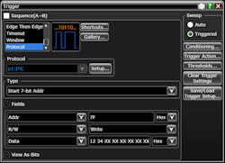
I want to set up my I2C trigger to only look at 7-bit addressed write packets with data[0] = 0x20 and data[1] = 0x21. Note that I have to tell the scope which protocol signals are connected to which scope input channels:
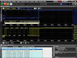
Typically, the trigger point (the instant the scope displays horizontally at t = 0.0 sec) for protocol triggers is the end of the last data you specified as a condition. In this example, the data[1] = 0x21 is the last condition we specified. Let’s zoom in horizontally and take a closer look at the trigger point.
It’s worth noting that placement of the trigger point, and reliable triggering and decode in general, relies on setting appropriate signal scale, offset, and trigger/decode thresholds. If you’re having trouble getting a protocol trigger to work correctly, check these settings before anything else! You will want to ensure that:
• All of the protocol’s input signals are scaled so that they use most of the scope’s vertical dynamic range (i.e., on a scope with eight vertical divisions, each signal should take up five or six divisions; it’s ok if they’re on top of each other).
• None of the signals are clipped on either the top or bottom of the screen (the signal trace shouldn’t touch the top or bottom of the display area)
• The thresholds for triggering and decoding (some scopes will use the same thresholds for triggering and decode; others offer separate thresholds) are set to the same value, and that the value is appropriate for the protocol (protocols may or may not specify vertical thresholds) and appropriate for the signal onscreen (should be roughly at the vertical midpoint of the signal).
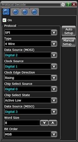
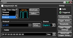
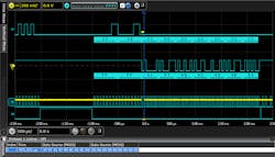
Example 2: Four-Wire SPI
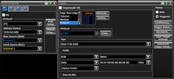
Some scopes allow the user to configure a protocol trigger on digital channels (also referred to as “MSO” channels, short for “mixed-signal oscilloscope”). This can be particularly handy when the protocol you’re working with involves a large number of signals. Let’s setup a four-wire SPI trigger:
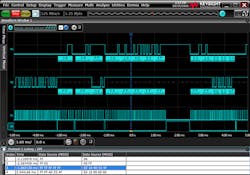
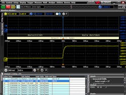
Now, let’s zoom in and take a look at the trigger point:
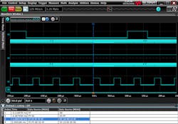
I know what you’re probably thinking: “What’s the point of using digital scope channels for triggering when the digital nature of these channels hides the analog signal behavior that I’m trying to see in the first place?”
Great question (you’re getting pretty good at this!). Using digital scope channels for protocol triggering is really useful when you want to trigger on protocol activity, but analyze analog phenomena on another channel. For instance, you may be interested in observing droop on a power rail when a certain packet is sent that enables a current-hungry device. Here, the ability to time-correlate and simultaneously view digital bus data and analog signals becomes a powerful weapon!
Hardware protocol triggers can be an invaluable tool in the quest to hunt down difficult-to-find behavior and correlate it with activity that perhaps seemed unrelated. If you do any significant amount of work with communications buses, do yourself a favor and check out the protocol-triggering options on your scope. Then do yourself another favor and stay tuned for the next article in the Oscilloscope Triggering Advanced Course, where we’ll discuss sequence triggering and software-search triggers!

About the Author
Colin Mattson
R&D Engineer
Colin F. Mattson is an engineer in Research & Development at Keysight Technologies in Colorado. Focusing on real-time oscilloscope trigger systems, Colin has been with Agilent/Keysight since early 2013. He received his BSEE/CE from Oakland University in 2012.
Comment About the Article
To join the conversation, and become an exclusive member of Electronic Design, create an account today!

Leaders relevant to this article: