Oscilloscope Triggering Advanced Course: Trigger Performance Characteristics
Download this article in PDF format.
Welcome to the Oscilloscope Triggering Advanced Course! In this series, I will walk you through the details of every corner of real-time oscilloscope trigger systems, and by the time we’re done, you’ll never need that AutoScale button again! Your co-workers will be stuck in the lab staring at auto-triggers all weekend while your scope is catching glitches and protocol packets automagically and emailing you the results! If you’re just joining us now, do yourself a favor and check out the first five articles in the series as well, to learn about advanced trigger modes, protocol triggering, trigger sequencing, and advanced trigger features.
In this final article of the series, we’re going to discuss trigger performance characteristics: How can we configure our trigger for optimum performance, what are the system settings that affect trigger performance, and what should we expect from the trigger system? Let’s get started.
System Overview
To understand what affects trigger performance, we first need to understand the trigger system itself. Because almost all modern oscilloscopes use analog trigger systems (Fig. 1), we’ll focus our discussion on those.
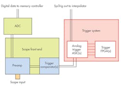
1. Here we see a simplified one-channel version of a generic digital-storage oscilloscope analog trigger system. In multi-channel scopes, there would be one “scope front end” box for each analog input channel, but still only one “trigger system” box (colored in red).
When you connect a signal to one of the input channels on your scope, the preamp for that channel is the first thing that sees it. It’s the preamp’s job is to scale and offset the signal appropriately so that it uses as much of the scope’s ADC range as possible while avoiding clipping. The preamp output heads off to the ADC to be digitized, but a copy of it is also piped into the trigger comparator(s) for the channel. The comparators look at the signal and decide if it’s above or below the threshold configured for that channel, and their output swings either high or low to denote that the input signal is either above or below the threshold.
It’s common to have multiple trigger comparators on a single channel. This allows the scope to implement trigger configurations that require more than one threshold on the same source channel (Edge Transition trigger, etc.).
The outputs of every trigger comparator on all channels are routed to what we’ll call the “trigger system” circuitry. This is a jumble of circuits that can include ASICs, FPGAs, and off-the-shelf components. Its job is to watch for the trigger event you’ve configured by observing the comparator outputs. The circuitry performs this “watching” by executing a complex logic operation on all of the inputs that participate in the trigger event.
The specifics of how trigger modes are implemented in this circuitry is beyond the scope of our discussion. It’s important, though, to realize that all of the analysis necessary to determine whether a signal satisfies a given trigger event is performed on the analog comparator outputs, not on digitized data stored in memory.
Note: Certain folks consider the output of a trigger comparator to be “digital” because some information about the original signal is lost in the comparison process (rise time, dc offset, etc.) and the output itself represents an inherently Boolean condition (either above or below the threshold). While this view is correct, when I talk about the trigger comparator outputs being “analog,” I mean that they are time-varying voltage levels on a board trace, as opposed to patterns of 1s and 0s stored in memory.
Now that we know what to do, let’s look at some of the system parameters that can affect trigger performance.
Trigger Thresholds
Trigger thresholds are the vertical levels that the comparators in the scope preamps compare the incoming signal against. Anytime you configure a level for edge trigger or set any other vertical adjustment in a trigger configuration, you’re adjusting a threshold. Careful threshold configuration is key for reliable trigger performance. If you’re setting up a trigger mode that uses only one threshold like edge or pulse-width, make sure that you set it in the middle of the vertical swing of the input signal (Fig. 2), unless you’re looking for some specific behavior that happens near the top or base of the signal.
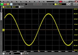
2. Shown here is a sine wave displayed on a Keysight Infiniium S-Series oscilloscope. Note the trigger threshold centered vertically on the signal. This threshold setting will yield optimal results.
The closer you set the threshold to one of the vertical extremes of the input signal, the less reliable your trigger will be. Poor threshold placement can also increase trigger jitter (Fig. 3).
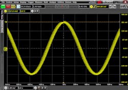
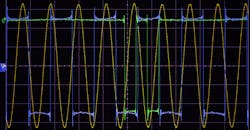
3. Here we see the same sine wave from Fig. 2, but the threshold has been moved to the top of the signal. Note the high jitter present in the signal’s horizontal position. Infinite persistence was enabled here to highlight the jitter.
It’s common for scopes to offer multiple thresholds per input channel. This is typically done to enable the scope to support trigger configurations that require multiple thresholds like Edge Transition or Runt trigger modes. In this case, be careful to configure both thresholds appropriately based on the mode.
Trigger Hysteresis
All electrical engineers are familiar with the concept of hysteresis (or should be), but many don’t realize that modern oscilloscopes take advantage of it to help the user filter out unwanted trigger events. Recall that the scope’s trigger comparators receive the output of the channel preamps.
If those comparators had no or very little hysteresis, and if the user configured the threshold at the center of the signal—the dc offset of the signal—then the comparator would fire on noise even when there was no other activity. Obviously, this isn’t helpful to users who want the trigger to tell the scope to only show them valid trigger events, so the trigger comparators used in scope preamps have some amount of hysteresis applied to them. Depending on the model of scope, this may be fixed, but often it’s adjustable.
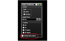
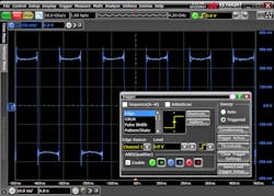
4. Here we see the Trigger Conditioning dialog on a Keysight Infiniium S-Series scope. Trigger hysteresis isn’t usually called out explicitly in user dialogs even when it’s user-adjustable. In this case, checking the Analog Noise Reject box will increase the hysteresis applied to trigger comparators associated with any analog channels that participate in the configured trigger condition.
Different scope models may present hysteresis adjustments to the user in varying ways, but in general, look for something in the trigger setup that talks about “sensitivity” or “noise-rejection” (Fig. 4). Higher sensitivity means less hysteresis, while lower sensitivity or more “noise-rejection” means more hysteresis. If you’re working with a particularly noisy signal, you may want to use more hysteresis to avoid false triggers. Conversely, if you have a marginal trigger case, either due to signal scaling or frequency content, you will probably want to use as little hysteresis as possible. We’ll discuss marginal trigger cases a little later.
Vertical Scaling
Aside from threshold configuration, appropriate vertical scaling of all signals involved in the trigger condition is probably the most important factor contributing to trigger performance, and it’s certainly the most often overlooked. The trigger threshold setting (at the preamp output /comparator input) and the amount of hysteresis applied to the comparator are a function of the vertical-scale setting on the input channel in question. As a result, those parameters will be most accurate relative to the signal if the signal uses as much of the vertical range of the scope as possible without clipping.
Let’s consider an example: I’m interested in observing three signals on my scope and I want to use two of those signals as part of the trigger condition. A common way to set this up is to turn on all three channels, and then use the vertical scale and offset settings of each channel to “stack” all three of them such that they’re all visible on screen at once and don’t overlap (Fig. 5). DON’T DO THIS—IT’S A BAD PROCEDURE. Keep in mind that the vertical scale and offset settings are not just display parameters; they are how the scope preamp is scaling the signal before outputting it to the analog-to-digital converter (ADC) and trigger comparators.
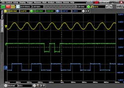
5. Three different signals, displayed simultaneously on an S-Series scope, are visible and don’t overlap because each signal’s scale and offset settings have been used to shrink and shift them to different parts of the screen. Unfortunately, configurations like this significantly reduce ADC resolution in the acquisition path while simultaneously reducing the accuracy of trigger threshold settings. Furthermore, if the signals are “shrunk” too much, their entire vertical range may be swallowed by the hysteresis band (which is configured based on full-screen range), unintentionally disabling triggers on that channel.
By shrinking the signals I’m interested in, so that they can all fit on screen without overlapping, I limit the resolution with which they’re digitized and potentially seriously handicap trigger performance. Not only will the accuracy of the trigger threshold placement on these signals be poor, I may not get a trigger at all due to hysteresis. It’s common for hysteresis to be set in vertical divisions relative to the full-screen vertical range. If I shrink my signal so much that it falls completely within the hysteresis band, the trigger comparators for that channel won’t fire at all!
So how should I set my scope up if I have multiple signals that I want to observe and trigger on? First off, I should scale all my signals so that they use most of the onscreen vertical range (Fig. 6). This will make sure that I’m getting good resolution on my scope’s ADC and good accuracy for trigger thresholds and hysteresis. If I’m OK with my signals overlapping, then I’m done.
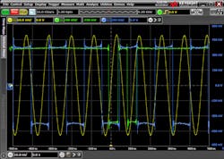
6. Here we see the same three signals from Fig. 5 appropriately scaled, but overlapping.
But what if I want to view them separately, or maybe just focus on one? Depending on the scope I’m using, I may have some options. First, some modern scopes have advanced display settings, separate from the vertical scale and offset settings, which I can use to move each signal into its own window on screen (Fig. 7). In this scenario, although the windows may be stacked and the signals will still appear to have a small vertical range, each window represents the full vertical range of the scope. Instead of changing the vertical scaling and offset of the signal at the preamp, I just changed how the signal is displayed on screen. If my scope has a feature like this, it’s probably my best option. If I’m not lucky enough to have a scope with advanced display features (and not lucky enough to have a boss that will buy me one), I can try one other trick.
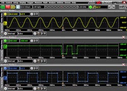
7. The same three signals from Figs. 5 and 6 are once again displayed on a Keysight Infiniium S-Series scope; however, this time we have configured the scope to display each signal in its own window. This allows us to scale each of the signals appropriately, using all of the available vertical range as in Fig. 6, but still avoid the signals overlapping in the display. Some scopes (including the S-Series) will even allow the user to drag some or all waveform windows onto external monitors if desired!
Assuming I’m only interested in observing the third signal and the first two are just there for the trigger, most scopes will allow me to trigger on channels that aren’t being acquired. To do this, I enable all three channels and scale them appropriately, configure my trigger event using the first two channels, and then I turn off the trigger channels while leaving the trigger configuration unchanged, leaving me with just the third signal remaining on the display (Fig. 8). Note that with this strategy, the first two signals aren’t being acquired at all, so if I need them for observation or measurements, this strategy won’t work.
8. This scope configuration displays channel three while triggering on channels one and two, even though those channels aren’t being acquired.
Frequency Response
It should come as no surprise to you that just like every other analog circuit in the world, the collection of hardware that forms the trigger system, preamp, trigger comparators, and trigger signal routing in your scope has a characteristic frequency response. What may surprise you is that this response is often quite different than that of the acquisition path in the scope. This isn’t an issue in lower bandwidth scopes, but it can be a source of frustration in higher bandwidth models, so it’s worth discussing.
As the acquisition bandwidths of high-performance real-time scopes have increased dramatically over the years, analog trigger-system circuitry hasn’t been able to keep pace. Unfortunately, this means that it’s common in higher-performance models for the scope’s acquisition system to have much higher bandwidth capability than the trigger system. While acquisition bandwidth is almost always printed right on the body of the scope itself, trigger-system bandwidth is usually hidden away in the datasheet.
If you’re interested in what kind of performance the trigger in your scope has, look in the datasheet for specs like “max edge trigger bandwidth” and “minimum glitch width.” Keep in mind that different trigger modes may have lower bandwidth than the ones listed; think of the listings as “maximum bandwidth.”
So why does the frequency-response difference between the trigger path and acquisition path matter? The answer is that most of the time, it doesn’t. For most cases, the trigger capabilities in modern scopes are more than enough for anything the user throws at it. But this isn’t the Oscilloscope Triggering Beginners Course, it’s the advanced course! Let’s consider a few scenarios that could lead to odd trigger behavior due to frequency-response differences between the trigger and acquisition paths.
Scenario 1—Super-Duper Fast Signals: If you have a high-performance scope and want to look at a fast signal, say something in the 18- to 20-GHz range, you may find that your scope can’t trigger on it at all. If it does, you may notice that it triggers marginally; i.e., the trigger rate is much less than you would expect, there seems to be very high jitter, etc.
As a fast signal passes through the circuitry leading to the trigger system, the highest band frequency components will be attenuated, eventually to the point of becoming undetectable. A good way to think about this situation is with a sine wave. As you increase the frequency of the sine wave, the amplitude will remain constant on screen (acquisition path), but the amplitude that reaches the trigger system will be reduced. If you increase the frequency beyond the capabilities of the trigger system, it effectively means that the signal has been attenuated in the trigger path to the point of being undetectable. If you’re looking at something other than sine waves, as most scope users do, attenuation of the higher band frequencies in your signal will mean that the edges reaching the trigger system won’t be as fast as those you see onscreen.
Scenario 2—DSP Response Correction: Let me tell you a dirty little secret: Oscilloscope preamps and signal paths aren’t perfect! I know, crazy, right??! Here in the R&D lab, we go to great lengths to present the most-accurate possible representation of the user signal on screen. One of the ways we do that is with every analog engineer’s favorite crutch trick: digital signal processing!
It’s not unusual for high-performance scopes to use DSP to correct the response of the acquisition path, showing the user the best possible representation of their signal as it exists at the scope input connector or even at the probe tip on some models. Unfortunately, because DSP is performed on digitized data stored in memory, the analog trigger path doesn’t get to have any DSP fun.
What this means is that if your scope uses DSP for response correction, acquisition bandwidth-limit filters, or any other purpose, the signal you see on screen may look different than the one seen by the trigger system. This will usually mean that the trigger system sees a signal with somewhat differently shaped edges and overshoot/undershoot than what you see onscreen. If you’re trying to trigger near the top or base of the signal, that’s when you’ll most likely notice differences between the acquisition and trigger paths due to DSP, which typically present themselves as an apparent error in trigger level at those extremes.
The best way to mitigate the effects of both scenarios described above is to follow the guidelines on vertical scaling and thresholds described earlier in this article. With appropriate scaling and thresholds, you stand to get the maximum performance possible out of your scope’s trigger system.
Congratulations! You have reached the end of (graduated?) the Oscilloscope Triggering Advanced Course! May you catch all of the glitches and protocol packets you seek! If you have questions, or if there are any other trigger topics you’d like to see covered in the future, please let us know in the comments!

About the Author
Colin Mattson
R&D Engineer
Colin F. Mattson is an engineer in Research & Development at Keysight Technologies in Colorado. Focusing on real-time oscilloscope trigger systems, Colin has been with Agilent/Keysight since early 2013. He received his BSEE/CE from Oakland University in 2012.
Comment About the Article
To join the conversation, and become an exclusive member of Electronic Design, create an account today!

Leaders relevant to this article: