Output Capacitance Optimization Using a Load Slammer—Theory
Part 1 of this series discussed what characteristics make up a good load slammer. This article discusses how to use load slammers effectively to design, evaluate, debug, and validate your on-board power source. In it, we will deal with:
- A quick survey of design and test tools.
- The nature of typical voltage regulators and how to exercise them for meaningful information.
- How a load slammer can be effectively used in the design and test process.
Designing Your Regulator
Fortunately, there are now many ways to get where you want to go with regulator design. For most simple converters (step-down, step-up, inverting), manufacturers have some sort of free vendor design software available. It may be as basic as a spreadsheet, or an integrated tool that will select and design your circuit for you. But the assumptions and shortcuts made in the software may not be obvious, so you won’t really know how well the design works until you test it out.
A second design method is design by FAE. If your company is large enough to get their attention, a distributor or factory FAE will be happy to design your circuit for you. If you buy their stuff. At their price. And if you are a design engineer, it takes all the fun out of cooking up your own secret sauce. But you will still need to test it to make sure it works right.
App note design works with many switching regulators as well, especially with constant on-time converters or converters with built-in loops. There may be a handful of equations to work through, or you may just follow the app note, enter the schematic, and lay out the board. So far, so good.
However, the actual loop may be unknown and therefore non-optimized for cost and performance. To validate it, you need to test it. Enter the load slammer, which can put a converter through its paces as you optimize output filter values.
Design Verification/Simulation
The next step up is using simulators, which come in various shapes, sizes, and price points. Make your choice and go for it. Simulation can be as simple or as involved as desired and can be very helpful, especially if the component models are accurate. It nicely complements testing with slammers to correlate real-world results with predictions.
A Bode analyzer is another applicable tool for testing and verification, if a bit expensive one. It’s mainly used for measuring loop gain of a power converter over frequency, but it can also be used for measuring impedance over frequency, including voltage regulator output impedance. Like load slammers, Bode analyzers provide valuable correlation with simulations and calculations. But slammers and Bode analyzers are very different—apples versus orangutans.
Bode analyzers are mainly small signal instruments that may not provide good large signal information. That is, a small signal loop bandwidth measurement may look good, but it doesn’t tell you how an output inductor affects response as it slews current up or down in response to a large load step. With current-mode loops, the inductor disappears in the small signal loop equation and becomes a current source. Unfortunately, it doesn’t really disappear—it just hides, waiting for a large transient to make its presence known.
A second large signal issue is nonlinearity in loops. That is, what happens when the loop responds improperly to a large transient and clips, distorts, or other. A transconductance error amplifier can easily saturate one direction or another in response to a large load step.
A third area is in testing hysteretic and semi-hysteretic (constant on time) converters. Sometimes it can be difficult (though not impossible) to get meaningful information from a Bode analyzer, as these converters are nonlinear and voltage/time-based.
Beyond that, many new controllers have nonlinear functions to improve transient performance during large signal events. These include multiple phases turning on at once, frequency bursts, pulse truncation, diode braking, and others. Their engagement thresholds are typically adjustable, and a small signal analyzer may not provide adequate insight into their operation.
Which brings us back to the load slammer. In its most basic operating mode, it doesn’t ask about the loop, just the results. However, slammers can be used with increasing levels of finesse to exercise and optimize converters. It cannot tell you what the whole loop response is, but it can provide a rough sense of phase margin1 as well as a general idea of the speed of the loop. It can even be used to measure output impedance. If you can afford a Bode analyzer, more power to you (pun intended). If not, you can still work out a good solution with a combination of software and slammers.
Lastly, the unspoken and assumed instrument in the room is the digital oscilloscope, which is the companion to the slammer to monitor regulator performance.
Using Load Slammers
How do we accomplish that? Effective use of slammers starts by understanding the nature of each voltage regulator and tailoring the test to that regulator. Here are some topics to understand, several of them interrelated:
- Small signal versus large signal
- Load step versus load release
- Load step size, starting load
- Modulation method
- Loop bandwidth
- Performance enhancing circuits
We’ve briefly touched on small signal versus large signal, but it’s worth mentioning again. For small load steps, the response will most likely be a small signal response. Increase the load step gradually, and the amplitude changes while the shape of the response stays largely the same. However, at some point the response may change more quickly, and in shape as well as amplitude. Observing this will give you an indication that a large signal phenomenon is at issue.
A typical example of this would be a buck converter with a high value output inductor that cannot slew past a certain rate (Fig. 1). Slew rate in di/dt is limited by V/L, even if the loop is very fast. Which brings us to the issue of load step versus load release.
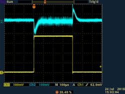
1. An example of a load step (yellow), and how that affects the regulator’s output voltage (blue).
Load step is a sudden increase in output load, while load release is a sudden decrease in load. For small steps, converter response to these two events may look very similar but can look very different as the step size increases. Why the difference?
Let us use an example of a buck regulator with 12-V input and 1-V output, using a 1-μH inductor. At maximum duty cycle, the converter can respond (if the loop is fast enough) to a load step at the rate of:
For load release, that number changes to:
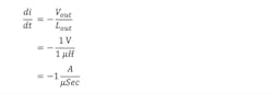
This is a full order of magnitude difference and will likely show up during large load transients. If you chose the inductor or know what its value is, the di/dt can be easily calculated and appropriate slammer settings (load step size and slew rate) can be chosen to fully exercise the converter.
Along with load step size, starting load is also important. Many converters have an operating mode for better light-load efficiency that consists of short bursts of pulses that are defined by voltage setpoints. Light-load efficiency improves significantly, at the cost of linearity in loop and transient response.
Modulation method is another consideration. Voltage- and current-mode converters have linear transfer functions but respond differently because of how they deal with output LC filter resonance. A voltage-mode converter tries to control ringing by pulling it inside the overall loop. A current-mode converter turns the inductor into a current source so that there’s no output ring.
For either of these methods, knowing loop bandwidth is critical to testing. This was touched on in the previous article regarding slew rates and transition times. Transition must be significantly faster than the loop response to get meaningful data. Vendors sometimes use this to their advantage when showing transient response in their datasheets. Transient response always looks better when the transition time is slower than the loop. Always check the specific test conditions and then run your own tests to verify or augment.
Semi-hysteretic converters (like constant on-time buck converters) modulate and behave very differently. Output voltage is sent to a comparator, usually through a divider. When divider voltage drops below a feedback threshold, a positive pulse is initiated. After a fixed on-time, the high-side switch turns off and waits for the feedback signal to tell it to initiate another pulse. Thus, there is no frequency loop, though loops can be added for better DC accuracy. Response to a load step can be nearly instantaneous, with load release at a slight disadvantage.
A good way to investigate this with a slammer is to synchronize the load step or release around the beginning or end of the pulse, adding variable delays to find worst-case response. Some slammers have a trigger input that can be connected to the switch node for such a purpose.
Performance-enhancing circuits are nonlinear additions to modulation (discussed earlier) that can aid transient performance. They may have an adjustable threshold that causes a response, like an extra pulse, or truncating a pulse, or diode braking. They usually deal separately and differently with load step versus release. This information will be in the datasheet of the regulator.
If a threshold is set too conservatively, not much is gained in performance. Too aggressive, and the circuit can experience strange interactions and instability. Simulation can be useful here if the model is sufficiently detailed. If not, slammers are excellent tools for optimizing and debugging. So how can a load slammer be best used?
Using Load Slammers Effectively
Let’s start with the following subjects:
- Where to place the slammer to greatest effect
- Where to measure output voltage and current
- How to measure output voltage and current
- Where to start in the testing process
Placing the slammer in the circuit is a bit like general board layout, where oftentimes everything seems to want to be in the same place. Nevertheless, best slammer placement or connection should be between the regulator and its primary load, which are hopefully close to each other.
Placement can be actual placement of a low-impedance connector on the board, with the slammer plugging in and out as needed. Many slammers are designed with this method in mind.
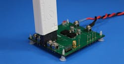
If there’s no connector, or no room for one, the connection to the board should be hardwired with short, wide strips of copper to minimize both resistance and inductance (Fig. 2).
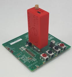
2. LoadSlammer soldered across the output capacitors.
As to measurement placement, preference depends on what you’re trying to accomplish.
From the perspective of the voltage regulator, the best places to measure voltage are directly at the input and output of the regulator (Fig. 3). This will provide highest efficiency numbers because there are no losses in the calculations from PCB trace resistance. Transient response tends to look better for the same reason, as the feedback sense point is typically (though not always) close to the output of the regulator.
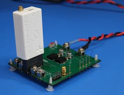
3. LoadSlammer using connector across the output of this two-phase regulator.
From a system viewpoint, the voltage at the load is all that matters. But it’s important to realize that if the regulator and load are in different locations, both places may need to be measured. Otherwise the regulator may be blamed for poor performance when it’s more a result of PCB trace resistance. Or, looking only at the regulator may lure you into a false sense of security because it looks good there.
Measuring voltage on the slammer may not be ideal, but it’s at least convenient if a test point is available, or if the slammer has its own ADC capability (Fig. 4).
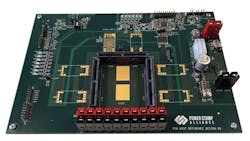
4. Multiple connectors are used for consistent evaluation and testing of ASIC transients.
As far as scope technique goes, if a differential probe isn’t available, then a coaxial socket for the probe, or very short ground leads can be used. Sometimes it’s helpful to loop the probe coax a couple of times through a ferrite clamp-on core (near to the scope) to reduce common-mode noise. Set the scope bandwidth for 20 MHz to get rid of high-frequency hash that can interfere with triggering and observation. Use scope cursors to get max and min values rather than relying on automatic measurements. Infinite persistence can be used to get maximum envelope if needed. Averaging (if the trigger is solid) can help dig signals out of the noise. Use enough acquisition samples to eliminate aliasing.
Measuring current is a separate challenge in that any sense method will introduce impedance into the system that interferes with system response. Current probes can be fast, but the loop has several nanohenries of inductance that will limit di/dt. Low-resistance current shunts add resistance and need compensation for their inductance, even for surface-mount chips.
Slammers are typically not calibrated, so their accuracy is also limited. My advice is to use an external load and/or shunt when making efficiency and DC measurements. For less than 10 A, a DMM is a good option. For low-cost bench work, you can short-term calibrate (not NIST traceable!) your shunt or slammer to the known DMM. But use good judgement.
For transient measurements, it’s therefore more difficult to get accurate current measurements, short of some expensive test equipment like a processor VTT (voltage test tool). Again, if budget is limited, slammers can still provide useful information for much less $$.
Load Slammer Testing
We continue with the types of testing that load slammers can do effectively.
Most slammers prefer low duty cycles (< 10%) to minimize continuous power dissipation; the first test is a fixed-frequency square-wave current step. If you know the loop bandwidth of the regulator, then set the frequency to 10% time to give adequate time for the loop to respond and recover.
If the loop bandwidth is unknown, start within the range of 100 Hz to 1 kHz and go from there. Set the load step size to a reduced percentage (50% is a good place to start) of the maximum load step requirement for the voltage regulator. Set the slew rate for the rated system requirement (if adjustable). Then adjust the scope trigger level for a good waveform.
If the regulator loop is too slow, slammer frequency may need to be lowered. However, for a fast regulator, slammer frequency may be increased so that the response time fills more of the scope display. Then increase the load to the maximum specified requirement and take measurements as needed.
This constitutes the most basic slammer function. However, as they say, “But wait, there’s more!” Here are some additional tests that can be useful.
First, to distinguish between small signal and large signal response, vary the step size to see how the waveform changes. Where small signal response is in control, the waveform shape stays the same while amplitude varies. When large-signal effects dominate, both the waveshape and amplitude change significantly. Slew rate may need to be adjusted as well to push inductor di/dt.
Some slammers can trigger on the switching waveform. For very fast converters, this allows the load transient to be adjusted to a worst-case point in the switching cycle.
Next, maximum slew rate can test the regulator decoupling solution beyond the loop bandwidth. Some of the ring may be passive rather than active.
Adjusting load step size and slew rate can be used to exercise converters with nonlinear performance enhancement features as discussed previously. Give a voltage-regulator threshold level, load step size can verify the real-world step size that activates that feature. The same goes for checking transient performance in and out of light load operation.
Slammers can even be used to measure output impedance over frequency. Set the slammer for 50% duty cycle and a step size that’s within the power rating of the slammer. Sweep the frequency over a range from a decade or more below the predicted loop crossover point to a decade above. See how the regulator output amplitude varies, especially around the crossover frequency. Some peaking will happen unless phase margin is better than 90°. A high Q peak will indicate lower phase margin or other potential instability. There may be some hash to ignore due to the square load step edges, though an adjustable slew rate can round these off some.
Two cautionary notes:
First, transient response can be highly affected by minimum load settings. If the minimum system load is too high for the thermal capacity of the slammer, an external resistor should be added. It only affects the DC level, so placement is not critical.
Second, when testing on board, the board load current must be considered for minimum loading, as well as for maximum loading that might push the regulator into current limit.
The upcoming third and final article in the series will provide examples of testing a typical buck regulator with a slammer.
For more on the LoadSlammer, go here.
Roger Beeston is the Founder of ProGrAnalog.
Reference
1. AN-1733 Load Transient Testing Simplified. Texas Instruments Application Report, SNOA507, November 2007.

About the Author

Roger Beeston
Founder and COO, Proganalog
Comment About the Article
To join the conversation, and become an exclusive member of Electronic Design, create an account today!

Leaders relevant to this article: