Welcome to the Oscilloscope Dojo: Become a Trigger-Fu Master
This file type includes high-resolution graphics and schematics when applicable.

Arguably, the most important capability of an oscilloscope is its ability to trigger on a signal. This ability, which we often take for granted or ignore in lieu of snazzier features, is fundamental to an oscilloscope’s ability to display a usable signal.
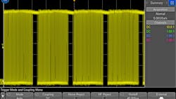
We’ve all (most non-millennials, anyways) had an analog scope sitting in front of us and seen the green line unintelligibly whizzing by in an unreadable fashion. While this is less common on today’s digital scopes thanks to modern triggering technology, effects like “ghosting” (Fig. 1) can still cause you grief while debugging your system. Let’s first look at how triggers work, and then explore some of the under-utilized trigger capabilities available that will make you a trigger-fu master.
What is a Trigger and How Does it Work?
Simply put, an oscilloscope’s trigger logic tells the oscilloscope when to trigger. In the case of a standard edge trigger, the trigger logic is just a comparator with a user-specified threshold level. If the input signal crosses from below to above (or above to below) the specified threshold voltage level, the scope will trigger and display the data. This threshold is often also referred to as the “trigger level” in the scope’s GUI.
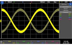
For more complex signals, there are still one or more relevant threshold values. However, the logic will be more complicated than a comparator. For example, a “rise time” trigger has two thresholds—a low and a high—that dictate the points from which the rise time is calculated (Fig. 2).
Understanding how these thresholds work is just the first step to mastering oscilloscope triggering. Let’s look at some other scope capabilities that will help you get to your signals faster.
Auto vs. Normal Triggering
Does the signal you’re trying to trigger on occur infrequently? Consider switching your oscilloscope out of “Auto” trigger mode and into “Normal” trigger mode. In auto mode, oscilloscopes will wait a specified amount of time and then trigger even if a valid trigger event wasn’t found.
Auto mode can be very useful when first probing a circuit or when browsing around a board, because you get instant insight into your signal and can adjust scope settings accordingly. But, if your trigger event happens at a slower rate than the scope’s “wait” period, you’ll get a mix of valid triggers and auto-mode-instigated triggers.
To avoid this, put your scope into normal mode. This will tell the scope to wait indefinitely for a valid trigger event and only display data when there’s a trigger event. Of note, you want to make sure your settings are properly configured in order to capture and view your triggered signal (which is where auto mode can be handy!).
Trigger Coupling
You probably knew that you could turn on ac coupling for your signal acquisition, but did you know you could turn it on for your trigger circuitry? You could even have the scope in dc-coupling mode, and the triggering in ac coupling. This puts a 10-Hz high-pass filter in the trigger path to eliminate any dc offset voltage. (This frequency is for Keysight InfiniiVision scopes; your mileage may vary.) Note, this is just for your trigger, so you’ll still be able to see the dc voltage on your scope screen.
Is that not quite what you’re looking for? Try turning on “Low Frequency Reject,” which is a mode designed to filter out low-frequency noise from your trigger path. This is also a high-pass filter, but with its corner frequency (–3 dB) at 50 kHz instead of 10 Hz. Only dc offset and extremely low-frequency noise will get filtered out with ac coupling, but enabling “Low Frequency Reject” will filter out low-frequency noise components like those from power lines, etc.
If that’s just the opposite of what you need and you’re having trouble with noise above 50 kHz, try using “High Frequency Reject” instead. This will turn on a low-pass filter on the trigger path that will filter out all of the high-frequency noise, creating a more stable trigger.
Maybe your unwanted noise has frequency components that are both higher and lower than the “frequency reject” capabilities of your scope, and you’re still seeing ghosting on your screen. Shucks, you’re going to have to get creative. Try using good ol’ “Noise Reject.” Noise Reject is an incredibly helpful tool that simply increases the hysteresis of the trigger circuitry. And that brings us to a quick discussion on trigger hysteresis.
The Effects of Trigger Hysteresis
When looking at hysteresis, we’ll go back to the example of an edge trigger for simplicity. Essentially, the comparator in the trigger circuitry has a “hysteresis band” that helps stabilize your triggers. Instead of just having one very specific threshold level for the comparator, the oscilloscope actually behaves as if it has two thresholds.
For example, if my scope is triggering on a rising edge with a trigger level of 1 V, my signal will have to go from 0.9 V to 1 V for the scope to trigger. It’s not enough for my signal to just dip from 1.01 V to 0.99 V and then back to 1.01 V. We intentionally introduce some hysteresis to help filter out unwanted trigger events.
Another way of looking at it is that there actually has to be an edge present; it can’t just be a small dip in voltage. Generally, this hysteresis is correlated to the vertical scaling of the scope. On our Keysight InfiniiVision oscilloscopes, the hysteresis is 0.4 vertical divisions. So, at 1 V per division, the hysteresis band is 0.4 V high. But, at 10 V per division, the trigger hysteresis is 4 V. This helps ensure that you’re getting valid triggers and no ghosting.
But, sometimes that’s not enough and you need something more. Maybe you’re using a clamp-on current probe or are in an extremely noise environment. That’s when you want to use “Noise Reject.” Noise Reject increases the hysteresis in the trigger circuitry. This helps eliminate unwanted triggers, but means you’ll need a larger (on screen) signal to get any trigger at all!
Bonus assignment: To see the effects of trigger hysteresis on your scope, put it in “rising or falling edge” trigger mode, and notice that your edges won’t align perfectly with the very center of the screen. They’ll be slightly offset to the right because the scope has to adjust the hysteresis band for both rising and falling edges. When it’s just set to trigger on one edge or the other, it absorbs the hysteresis above or below the center point on screen and you won’t see this effect.
Trigger Holdoff
It woudn’t be fair to talk about advanced trigger modes without discussing holdoff. It’s been around since the days of analog scopes, and can be very useful under the right circumstances. Trigger holdoff is extra helpful when looking at digital bursts, but can be utilized for any periodic signal. Essentially, trigger holdoff modifies the re-arm time of the oscilloscope’s trigger.
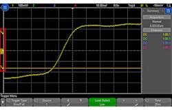
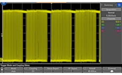
Generally, a scope will try to capture data as fast as possible. When it gets an acquisition, it will re-arm and prepare for a new trigger event as fast as its circuitry will allow (search “waveform update rate” for more on this). But, setting a holdoff value will tell the scope to intentionally wait longer than it needs before re-arming the trigger. Why is this useful? Taking a digital burst as an example, it’s possible that the scope will re-arm its trigger right in the middle of a burst. This means that the signal on screen is going to jump left and right as the scope triggers on different portions of the packets (Fig. 3).
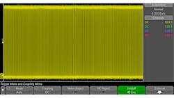
However, if you were to set a trigger holdoff just lower than the packets’ frequency of occurrence, you’ll always trigger on the first edge in the packet and the waveform will be stable (Fig. 4). Holdoff can be useful for any repetitive signals, but is most often used with digital buses and bursts.
External Trigger Input
Finally, if all of the above doesn’t meet your needs, you can use an external trigger input to trigger the scope from another source. This could be another piece of equipment or another signal from your device. Get creative!
How’s Your Trigger-Fu Now?
With this information, you should be able to overcome a lot of different annoyances that cause trigger issues. Coupling these abilities in with your oscilloscope’s advanced trigger capabilities, you should be able to get a stable, useful trigger on any signal.

About the Author

Daniel Bogdanoff
Oscilloscope Product Manager
Daniel Bogdanoff is the Product Manager for the InfiniiVision series of oscilloscopes at Keysight Technologies. He graduated from Texas A&M with a degree in electrical engineering. In his spare time, Daniel enjoys whitewater kayaking, mountain biking and playing various musical instruments.
Comment About the Article
To join the conversation, and become an exclusive member of Electronic Design, create an account today!

Leaders relevant to this article: