What’s the Difference Between a DSO and DPO?
This file type includes high-resolution graphics and schematics when applicable.
DSO stands for digital storage oscilloscope. DPO stands for digital phosphor oscilloscope. A DPO is also a DSO. And a DSO can also be a DPO. So what exactly is a DSO and what is a DPO?
A DSO is typically a real-time sampling oscilloscope. Real-time sampling simply means that the scope is able to capture signals in a single acquisition utilizing a high-sample-rate analog-to-digital converter (ADC). In other words, a DSO doesn’t utilize repetitive acquisitions to “build-up” sufficient samples to represent the signal under test (equivalent-time sampling), although this isn’t a hard-and-fast rule.
As mentioned before, a DPO is also DSO. But a DPO adds one additional element that allows it to better represent the signal’s third dimension. The first two obvious dimensions are voltage and time. The third and less obvious dimension is frequency-of-occurrence, which is represented by trace intensity on a scope’s display.
Learn more about oscilloscopes
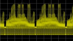
1. Analog oscilloscopes could display a range of trace intensities, especially for complex-modulated analog signals.
If you can remember back to the old analog scope days, you may recall that these oscilloscopes were able to display a range of trace intensities. This can provide valuable insight into the true analog characteristics of a signal under test. This is especially true for complex-modulated analog signals (Fig. 1), as well as for digital signals that contain varying degrees of noise and/or jitter.
With older analog scope technology, trace-intensity variation was a natural phenomenon based on how much time the electron beam remained within a XY region on the inside face of the cathode ray tube (CRT). The inside face of CRTs of analog oscilloscopes are coated with a material called phosphor. When electrons strike the phosphor, the phosphor begins to glow. The more electrons that strike the phosphor in a given region of the CRT for a given amount of time, the brighter the phosphor glows.
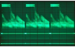
2. The original DSOs were not able to display trace intensity.
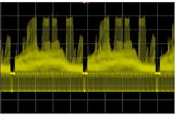
When DSOs were birthed in the early 1980s, this third dimension of trace intensity was initially lost (Fig. 2). As technology progressed, oscilloscope vendors developed a technique that could closely emulate the display quality of analog oscilloscopes utilizing digital signal processing to bring the third dimension back (Fig. 3).
Basically, by counting the number of hits (digital samples) in particular XY regions of a bitmap—sometimes called buckets—pixel intensity could be digitally modified to represent trace-intensity modulation of phosphor. This is the genesis of the term digital phosphor oscilloscope (DPO).
3. Modern oscilloscopes use digital signal processing to show trace intensity.
So why don’t companies like Keysight have DPOs listed in their product repetoire? Actually, they do. But they don’t call them DPOs. Nearly all of Keysight’s DSOs employ trace-intensity modulation. In fact, the company’s oscilloscope display technology is claimed to offer the highest-quality trace-intensity modulation, thanks to fast waveform update rates with deep memory acquisitions. This provides more hits in XY regions (buckets) in a shorter amount of time to provide a higher level of statistical information upon which to base pixel intensity.
Learn more about oscilloscopes
About the Author
Johnnie Hancock
Johnnie Hancock, product manager at Keysight Technologies Oscilloscope Products Division, is currently responsible for worldwide application support activities that promote Agilent’s digitizing oscilloscopes. He began his career with Hewlett-Packard in 1979 as an embedded hardware designer and holds a patent for oscilloscope trigger hysteresis calibration. He holds a degree in electrical engineering from the University of South Florida.


