Why You Should Care About Oscilloscope Trigger System Basics
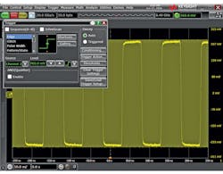
You sit down at your lab bench to debug some funny behavior in a 10-MHz clock. You fire up your oscilloscope, get your probing in place, and hit the almighty Auto Scale button, after which you’re presented with something like what you see in Figure 1.
Then it strikes you—there are ten million clock cycles occurring every second! How is the oscilloscope able to accurately display such a clean representation of your signal? How is it that the middle of the rising edge of your clock is perfectly aligned at center screen? The answer is the trigger system.
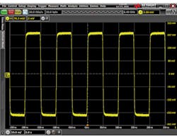
1. Using Auto Scale on the oscilloscope produces this view of a 10-MHz square wave.
The trigger system is both one of the most commonly used and least-understood subsystems in real-time oscilloscopes. In this article I’m going to pull back the curtain just a bit, and explain what the trigger system does, how it works, and why you should care.

What It Does
The sole responsibility of the trigger system is to tell the rest of the oscilloscope what data to care about. It decides when the acquisition system begins acquiring, which means that by default it decides what’s displayed on screen and what data is available to make measurements on. It can make these decisions with a very simple set of conditions or very complex conditions, based on user input. Let’s consider the example in Figure 1, a 10-MHz square wave. The reason the signal in the image looks so clear and well-positioned on-screen is that the trigger is set up, appropriately, to look for a rising edge on Channel 1, as seen in the trigger configuration dialog in Figure 2.
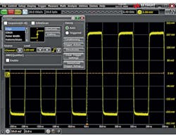
2. Auto Scale automatically configures the oscilloscope to trigger on the rising edge of Channel 1.
Remember that to start, we used Auto Scale, which chose an appropriate trigger source and threshold based on our input signal. But what would our signal look like without an appropriate trigger configuration?
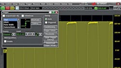
In Figure 3, I changed the trigger condition to look for an edge on Channel 2 (which has no signal connected at the moment). The auto-trigger feature, which we can see is enabled in the “Sweep” section of the trigger configuration dialog, is automagically kicking off acquisitions on a regular time interval, giving us a smear of yellow signal trace across the screen.
3. An inappropriate trigger configuration will cause triggers to occur on a predetermined time interval, regardless of signal behavior if auto-trigger is enabled, as seen here. Infinite-persistence has been enabled on Channel 1 to better illustrate what is occurring.
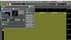
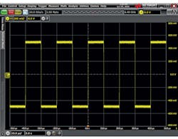
The signal itself appears to be clearly visible in this image, superimposed over the “smeared” signal trace. Unfortunately, this is just an artifact of the screenshot; that’s where the signal happened to line up at the instant I took the screen capture. In practice, auto-triggered acquisitions are only useful in determining the relevant dc parameters to use in setting up your trigger condition. Note that if the auto-trigger feature is disabled, without an appropriate trigger configuration, the scope simply won’t acquire (Fig. 4).
4. Disabling the auto-trigger feature without an appropriate trigger configuration means the oscilloscope won't acquire at all.
The trigger system will always place the trigger point (the instant at which all conditions present in the trigger configuration are met) at t = 0.0 s on-screen. Later on, we’ll see how using advanced trigger configurations can help capture infrequent and hard-to-find events, in addition to the simple rising-edge trigger we’ve seen so far.
How It Works
Most real-time oscilloscopes have an “analog” trigger system. This system is actually a mishmash of analog circuitry and digital counters, but it relies on input from analog comparators fed from the scope preamplifier. Some oscilloscopes now feature a “digital” trigger, meaning that the trigger system is entirely digital and is fed with integer data from the analog-to-digital converter (ADC) output.
Both types of systems perform the same function; evaluating whether or not all of the configured trigger conditions are met at a given moment in time. Because fully digital trigger systems are fairly rare, we’ll focus on analog trigger systems.
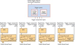
5. This diagram depicts a simplified view of the analog channel front-ends and trigger system in a generic four-channel digital storage oscilloscope.
Figure 5 shows a generic representation of the parts of a four-channel DSO (digital storage oscilloscope) that we’re concerned with—the analog channel front-ends and the trigger system. The trigger system takes inputs from comparators on all of the analog channels and provides a single output. For convenience, let’s focus on a simplified diagram with only one analog channel.

6. This diagram depicts a simplified view of a one-channel digital storage oscilloscope's analog channel front-end and trigger system.
Figure 6 is a simplified, one-channel view of the same systems depicted in Figure 5. When a signal is connected to the channel input it goes through a series of transformations before it ends up on-screen:
- First, the signal is scaled appropriately and offset if necessary by the preamp. The preamp output is sent to the ADC to be digitized.
- Trigger comparators observe the output of the preamp and fire if it exceeds their set threshold. This threshold is set based on user input, or by helper routines like the almighty Auto Scale.
- The trigger system observes all of the trigger comparator outputs in the system and combines them in such a way as to monitor for a given set of conditions. These conditions can be very straightforward (i.e., rising edge on Channel 1) or quite complex (i.e., pulse-width greater than 2.4 ns on Channel 3, followed by a pattern of Channel 1 high, Channel 2 low, and Channel 4 low, held for a duration of greater than 30.0 ns and less than 50.0 ns).
- When the trigger system sees that all of the conditions are met for the specified trigger, it sends a pulse on its output. We call this signal “System Trigger” or “SysTrig” for short. SysTrig is monitored by the acquisition system as well as a special subsystem known as the “time-base interpolator.”
- When the acquisition system sees a pulse on SysTrig, it begins to digitize, process, store, measure, and finally display data. We refer to this entire process in general as “acquisition.”
- • Before the acquisition data (the waveform), which is now stored in memory, can be displayed on-screen, we need to know how to orient it horizontally. This is where the time-base interpolator comes in. The interpolator monitors SysTrig, just like the acquisition system. When it goes high, it’s the interpolator’s job to figure out what address in waveform memory matches up with the instant the trigger occurs.It communicates this information to the acquisition system and voila, the result is the desired waveform on-screen, with the trigger point placed perfectly at t = 0.0 s!
Why You Should Care Triggering
Although some may find the inner workings of oscilloscope subsystems interesting, it’s fair to say that most folks couldn’t care less. If you’re one of those people and you just skipped the entire “How It Works” section above, no sweat, there will not be a quiz at the end! The bottom line is that you should care about the trigger system and take the time to understand it, because it can help you debug difficult issues and save you quite a bit of time and frustration.
Using an oscilloscope in a basic way—that is to say, pushing the Default Setup and Auto Scale buttons—can tell you a little bit about your signal and is a quick and convenient way to get started. However, if you’re interested in capturing an infrequent event, as is often the case when debugging common issues like runts, glitches, and setup-and-hold violations, the trigger system is a powerful tool.
What About Advanced Trigger Modes
In addition to edge-trigger mode discussed at the beginning of this article, most real-time oscilloscopes have a number of advanced trigger modes designed to detect common problems. When used in conjunction with “Triggered” sweep (aka, auto-trigger disabled), these modes will ensure that only the behavior you’re looking for is acquired and displayed. As an example, let’s look for a runt in a square wave. We connect our signal and use our trusty Auto Scale button, and all we see is a square wave. No runt in sight!
7. Edge-trigger mode isn't a good tool to use when searching for runt events in your signal.
Figure 7 shows us that although we suspect a runt is present in our signal, finding it with edge trigger will prove difficult. We can try zooming out a bit.
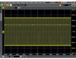
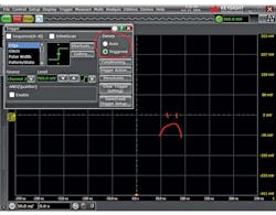
As shown in Figure 8, by zooming out horizontally, we can tell that there’s something fishy going on, but it’s not entirely clear what. Now, let’s use runt trigger mode on a Keysight Infiniium S-Series oscilloscope and see what we can find (Figs. 9 and 10).
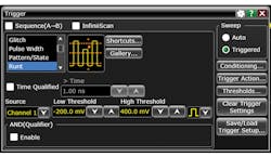
9. Runt-trigger mode setup on a Keysight Infiniium S-Series oscilloscope.
There’s our runt! The waveform in Figure 10 is clear and steady, and the event we’re interested in, our elusive runt, is right at t = 0.0 s! This is the value of learning the trigger system on your scope. It will allow you to find the events you’re interested in, and only the events you’re interested in, very quickly. Although this example focused on finding a runt, the same sort of example can be demonstrated with glitches, setup-and-hold violations, specific data across multiple channels, data patterns relative to clock edges, edge transition times, etc., using the appropriate trigger mode.

10. Runt-trigger mode quickly identifies and displays the runt event in the signal.
Advanced Trigger Features
In addition to advanced trigger modes like runt mode discussed above, many oscilloscopes have features that can be used in conjunction with trigger modes to further refine what we want the scope to show. They can also instruct the scope to automatically take actions when a trigger occurs.
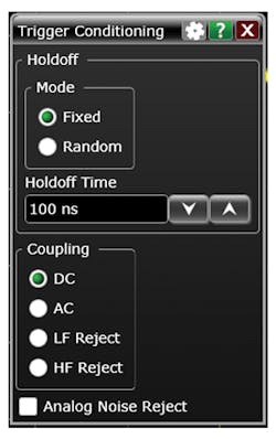
11. Refine what the oscilloscope displays in a trigger by using the Trigger Conditioning dialog, shown on a Keysight Infiniium S-Series oscilloscope.
Figure 11 shows some common options for trigger conditioning, while Figure 12 shows some of the things we can configure the oscilloscope to do for us automagically when a trigger occurs. My personal favorite is the “Email on Trigger” feature. If you have a really infrequent event, that’s no problem—set up your trigger and leave for the weekend. Come back, open up your email, and find all of the data you need!

12. A wide variety of trigger actions are available on a Keysight Infiniium S-Series oscilloscope.
Your Evenings and Weekends Will Thank You
The trigger system is a mystery to many engineers, but it doesn’t have to be a mystery to you. Make a point to learn the trigger system on your scope today and you may find yourself with quite a bit more free time in the near future!
Read More About Oscilloscopes


About the Author
Colin Mattson
R&D Engineer
Colin F. Mattson is an engineer in Research & Development at Keysight Technologies in Colorado. Focusing on real-time oscilloscope trigger systems, Colin has been with Agilent/Keysight since early 2013. He received his BSEE/CE from Oakland University in 2012.
Comment About the Article
To join the conversation, and become an exclusive member of Electronic Design, create an account today!

Leaders relevant to this article: