
Members can download this article in PDF format.
Portable and mobile products require sophisticated battery-management circuitry to extend battery life and avoid unexpected shutdowns. A key battery-management component is the battery gauge, which uses voltage and current measurements to calculate such essential parameters as state of health (SOH), remaining battery capacity, and state of charge (SOC), or conversely, the depth (or degree) of discharge (DoD).
Traditional battery gauges model a battery as a simple low-frequency RC network, which is sufficient to make highly accurate SOC estimations for slowly varying loads. However, a slew of emerging artificial-intelligence (AI)-enabled products as well as established products like drones, power tools, robots, and e-bikes can experience rapid fluctuations in load currents that complicate predictions of remaining battery life.
Sponsored Resources:
- Redefining Battery Accuracy
- TI's Portfolio of Highly Accurate Battery Gauges
- Learn More about Dynamic Z-Track™ Technology
To provide accurate gauging for such products, Texas Instruments developed the Dynamic Z-Track algorithm, which delivers accurate SOC, SOH, and remaining-capacity estimations for batteries experiencing rapidly varying load currents.
The algorithm uses a broadband battery model that simulates voltage transients and dynamic current profiles to enable real-time resistance measurements even with rapidly varying currents. The company offers battery-gauge devices that implement the algorithm, simplifying efforts to optimize battery-life estimation in your designs.
Resistance Measurement
For any battery gauge, accurate measurement of the battery’s series resistance (RS in Figure 1) is critical. Series resistance can vary for several reasons, including ambient temperature and the battery age.
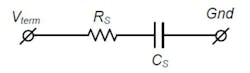
Figure 2, for example, shows how one lithium-ion battery’s resistance increases with the number of charge/discharge cycles.
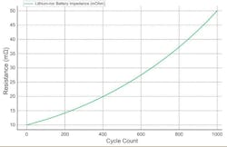
Figure 3 illustrates the general approach to remaining-battery-capacity estimation. First, the battery gauge is programmed with the minimum voltage required to safely and reliably operate the end-product (the dashed blue line at 3 V). Next, it can measure the battery open-circuit voltage (OCV), represented by the black curve in the figure, when load current is zero.
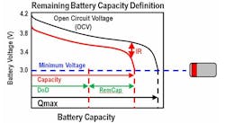
Then, the gauge measures the load current, followed by the battery terminal voltage (red curve) corresponding to the measured load current, allowing it to determine the resistance and the IR drop. Finally, it can determine the DoD and remaining battery capacity (green arrows in the figure). Note that a gauge which ignores the IR drop completely would greatly overestimate the remaining battery capacity (black arrow).
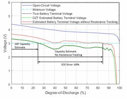
In addition to accounting for the IR drop, a gauge should accurately track resistance changes. Without resistance tracking, a gauge can seriously overestimate the remaining capacity. Consider the example in Figure 4, based on a 1.75C load current at a 25°C ambient temperature. The Dynamic Z-Track algorithm (whose performance is represented by the green DZT curve) closely tracks the black true battery-terminal voltage, enabling an accurate estimate of remaining capacity, while an algorithm without resistance tracking (the red curve) overestimates remaining capacity by 60%.
Real-time resistance tracking, though, presents its own challenges when load currents vary significantly. Consider, for example, a battery experiencing a C/2 step in load current. (A 1C current indicates the current level necessary to fully charge or discharge the battery in one hour, so a C/2 rate indicates the current level needed to fully charge or discharge the battery in two hours.)
In response to the C/2 step, the resulting battery voltage transient may require several minutes to settle out, and traditional low-frequency impedance-tracking gauge algorithms can’t accurately measure resistance during this time. In contrast, the high-bandwidth Dynamic Z-Track algorithm is able to update the resistance during voltage and current transients.
Battery-Gauge Devices
Texas Instruments offers a complete portfolio of battery-gauge devices for applications ranging from robotic vacuum cleaners to energy-storage systems.
A recent addition that makes use of the Dynamic Z-Track technology is the BQ41Z90 battery gauge and protector, which supports from 3 to 16 cells in series in Li-ion, LiFeP4, NiMH, and Li-polymer battery packs. In addition to offering Dynamic Z-Track technology, it provides cell balancing with up to 50-mA bypass capability per cell. Five general-purpose input/output (GPIO) lines can be configured for driving external LEDs.
The BQ41Z90 employs an 18-bit, integrating, delta-sigma analog-to-digital converter (ADC) in conjunction with an external sense resistor down to 0.25 mW to measure current. A second 16-bit delta-sigma ADC measures battery and individual cell voltages. The device also includes an internal temperature sensor and inputs for four external negative-temperature-coefficient (NTC) thermistors.
The device can communicate over an SMBus v3.2 interface or an I2C interface. It also incorporates a variety of safety functions, including overtemperature and overvoltage protection as well as overcurrent protection in both charge and discharge modes.
To optimize power savings, the device has multiple power modes. In active mode, the CPU, ADCs, and protection functions are on, and typical current draw is 500 µA with no communication. In sleep mode, the ADCs and protection features remain on, but the CPU is halted, and typical current draw is 250 µA.
A deep-sleep mode powers off most functions but retains data in RAM; typical current draw is 80 µA. A hibernate mode reduces typical current draw to 30 µA by powering off everything except the battery-pack-detection and wakeup functions. And finally, shelf and shutdown modes reduce typical current consumption to 3 µA and 0.6 µA, respectively.
For applications that require fewer cells, the company offers the BQ41Z50, which applies the Dynamic Z-Track technology to battery packs with two to four cells in series. It provides cell balancing with up to 25-mA bypass capability per cell.
Conclusion
Unpredictable loads complicate the process of estimating remaining battery life. TI offers the Dynamic Z-Track algorithm to accurately calculate SOC and SOH despite widely varying load currents. The algorithm finds applicability in a variety of applications, including drones, e-bikes, robots, and AI-enabled tablets and laptops.