Safety MCUs Enable Precise Steering and Smart Braking
Members can download this article in PDF format.
As pure mechanical and hydraulic linkages recede from dominance in the automotive industry, automakers are moving to electronic and electromechanical solutions. A detailed look at braking and steering systems illustrates how you can get started on successful intelligent-chassis designs. These include automotive-grade components such as real-time microcontroller units (MCUs), sensor interfaces, power-management integrated circuits (PMICs), and data-communications channels.
Electromechanical Braking
In a brake-by-wire electromechanical brake (EMB) system (Fig. 1), a fully electronic interface replaces the hydraulic linkage between the in-cabin brake pedal and the brake itself. EMB eliminates hydraulic fluid and pipelines as well as vacuum boosters, saving weight and maintenance costs while freeing up cabin and chassis space for additional comfort and functionality. In addition, EMB can respond in about half the time of conventional braking.
Sponsored Resources:
- Design more precise steering systems
- Design smarter braking systems
- Safety MCUs for next-generation chassis designs
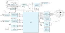
When a driver actuates the in-cabin EMB pedal, pedal sensors detect the position and force, while springs or motors provide force feedback to give the driver the feel of a conventional brake pedal. Based on pedal status and road-wheel speed feedback, an electronic control unit (ECU) communicates the required braking force to the wheel-end actuators, which use electric motors to apply the appropriate force required for friction braking.
For an electric or hybrid-electric vehicle, a separate ECU will determine the optimal balance of friction and regenerative braking. In addition, for autonomous vehicles and vehicles with advanced driver-assistance system (ADAS) features such as automated cruise control, the wheel-end brake actuator can accept braking inputs from a separate controller.
To help you get started with braking-system designs, Texas Instruments offers the TIDA-020106 EMB reference design. It illustrates hardware and software development in accordance with the ISO 26262 functional-safety standard up to the stringent Automotive Safety Integrity Level D (ASIL D). The design is compatible with 48-V as well as 12-V electrical systems.
Key TI components include an F29P329SM2 MCU, a TPS653860-Q1 PMIC, a pedal-position interface such as the LDC5072-Q1 inductive position-sensor front end, and various communications interfaces. A DRV3263-Q1 48-V three-phase gate driver can drive six MOSFETs configured to deliver power up to 500 W to a brushless DC (BLDC) motor. The company has developed and assembled a board based on the reference design for testing and validation purposes (Fig. 2).

Electronic Steering
An electronic steering system consists of two primary subsystems: the hand-wheel actuator (HWA) and the road-wheel actuator (RWA). The HWA employs angular-position sensors to detect the driver’s steering inputs, and it generates a force feedback that mimics the feel of a conventional mechanical steering system.
The RWA complements the HWA. It takes the electronic steering command from the HWA, or from a central steering control unit in the case of autonomous or ADAS operation, and actuates the steering rack. It also acquires road-wheel feedback such as cornering resistance and communicates it back to the HWA, which contributes to the HWA’s force feedback to the driver.
Figure 3 shows the basic circuit blocks that make up the RWA. (The HWA incorporates similar blocks.) In the center of the diagram is the isolation subsystem. It includes devices such as the ISO6442-Q1 four-channel isolator to provide galvanic isolation between two redundant RWA systems that may have different ground potentials. In the diagram, the two redundant systems form mirror images of each other across the isolation barrier illustrated by the vertical dashed red lines.
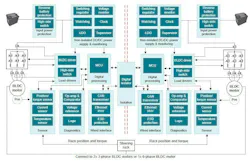
Subsystems within the mirrored redundant systems include the input power protection subsystems (top left and top right), which incorporate components such as LM74502-Q1 ideal diodes to provide reverse-polarity and overvoltage protection. The power-protection subsystems connect to the non-isolated DC/DC power-supply and monitoring systems (top center left and top center right). These integrate products such as the LM68645-Q1 synchronous functional-safety buck converters to develop and monitor multi-rail voltages for sensors, actuators, and other electronic components.
In the center row, load drivers power the BLDC steering motors in response to control signals from the MCUs. On the bottom row, the sensor subsystems measure parameters such as angle, torque, position, motor current, and temperature, all of which serve as inputs to the MCU. Also in the bottom row, the diagnostics subsystems can monitor system status and help establish a safe state in the event of a fault.
The final subsystems are the wired interfaces, which enable communications with other systems over interfaces such as CAN and Ethernet.
Automotive-Grade MCUs
Automotive systems such as those for EMB and steer-by-wire require functional-safety-compliant MCUs like the F29H85x, F29P58x, and F29P32x, which are all members of TI’s C2000 family. These devices have very-long-instruction-world (VLIW) architectures that supports 16-, 32-, and 48-bit instructions. Each includes a byte-addressable CPU and a linear memory map with a 6-GB address range. A fully protected nine-stage pipeline ensures that read and write operations occur in the proper order.
To boost compute speed and throughput, the devices can fetch up to a 128-bit instruction packet every cycle. In addition, they can execute fixed-point, floating-point, and memory operations in parallel, including trigonometric and vector-translation operations for optimizing real-time control.
To support ASIL D functional safety, the devices offer a lock-step core for redundancy, and they include integrated error-correction-code (ECC) logic as well as integrated memory-management and protection mechanisms. Separate code threads are fully isolated and protected. The devices support multizone security in hardware, with an individual password for each zone to control access. To enhance debug, the devices include data-logging and code-flow trace instructions, with trace data logged to on-chip memory or exported through serial ports.
Conclusion
Steer- and brake-by-wire systems offer advantages in responsiveness, reliability, and safety as well as size and weight savings. TI offers automotive-grade components ranging from ideal diodes to MCUs for such systems, as well as reference designs and a comprehensive software and toolchain ecosystem to help you get started on your own designs.