
Multi-Axial Coreless Hall-Effect Current Sensor Redefines HEV/EV Traction Inverter Design
Members can download this article in PDF format.
Traction inverters lie at the heart of today’s hybrid and electric (HEV/EV) vehicles. They had a humble beginning in the 1960s, though, when the shift from DC-DC converters to DC-AC converters came about in early EV prototypes.
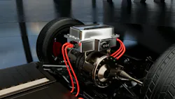
This shift was necessary because DC-DC methods could not support the evolving applications that were being implemented as the segment advanced. The need for AC converters was quickly realized. From those early days to today’s new and innovative traction inverters, such as Texas Instruments’ MCS2100-Q1 (Fig. 1), the industry’s first multi-sensor, multiaxial Hall-effect current-sensor traction inverter, they’re meeting the critical demands of high-performance, high-reliability, minimal footprint solutions.
Sponsored Resources:
Inverter 101: Single- and Multi-Axis Coreless Traction Inverters
Traction inverters have the job of converting power from the EV’s electrical system to motor torque. This process requires that these inverters maintain precise control of the drive motors. As a result, there’s very little room for error within the motor-phase current, the most affected element of inverters. Even minor measurement errors adversely affect the torque control loop, resulting in torque ripple, vibration, uneven acceleration, and noise, all of which adversely affect performance and safety.
Until recently, the accuracy was achieved with magnetic core sensors that measured current in a single direction. While this provided satisfactory results, it was always haunted by size and weight. And with today’s powerful EVs, and voltages of 800 V, this became challenging. It was time to rethink inverter design to meet mission-critical accuracy at these high voltages.
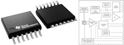
After extensive design collaboration, the team adopted a coreless, multi-axial approach that measures magnetic-field components in multiple directions rather than along a single axis. The TMCS2100-Q1 programmable, coreless, high-precision Hall-effect current sensor, was the ideal component for the job (Fig. 2).
However, there were challenges. Without a magnetic core, accurate current measurement becomes more difficult. The solution was to calibrate the Hall-element sensor at a specific position relative to the current-carrying conductor. Because the magnetic field at the sensing element changes with distance from the conductor, any displacement produces a corresponding change in the measured field.
The resulting displacement-related error can therefore be analyzed to establish a relationship between the magnetic-field variation and the physical position of the components. In this way, the sensor’s magnetic response can be used to determine position or displacement.
Measuring Magnetic Fields in Multiple Directions
The multi-axial coreless Hall‑effect current sensor senses current by measuring magnetic-field components in multiple directions, combining them into a vector. It then applies advanced algorithms to cancel errors and interference. The result is precise, reliable current measurement without the size, weight, and mechanical complexity of magnetic cores, while meeting the stringent accuracy needs of today’s EV and HEV vehicles.
The high sensitivity of today’s sensors can measure the slightest movement within the conductor. Some of this movement is unwanted. By having dual axes, not only is accuracy improved, but the principle of signal cancellation can be applied.
In the case of the TMCS2100-Q, displacement errors can be less than 1% at 0.4-mm movement and as low as 0.25% at 0.1 mm. This level of precision improves the EV powertrain torque control loop, maximizing efficiency and power delivery across varying load and thermal conditions.
In a multi-axial sensor, the Hall-effect element senses two orthogonal magnetic-field components. These are typically the X-axis (horizontal) and Z-axis (vertical). Combining these measurements improves motor-phase current accuracy, giving the traction inverter more precise feedback for torque control. More accurate current feedback helps reduce torque ripple, vibration, and acoustic noise, thereby improving system efficiency.
Dual-axis measurement also reduces magnetic crosstalk. The sensor combines the X- and Z-axis magnetic-field readings and applies a crosstalk-rejection algorithm to distinguish the target current from nearby magnetic interference. Because the coreless package is smaller and lighter than a magnetic-core assembly, it can also reduce mechanical loading while the dual-axis measurement compensates for displacement-related errors.
This multi-axial design can achieve 20X greater accuracy than previous single-axis coreless designs. Also, a multiaxial sensor’s position relative to the busbar is important. Earlier iterations required busbar modifications such as notches, slices, or holes, which can complicate thermal management. This approach removes that requirement, allowing designers to have more options with mechanical layouts, resulting in better board space optimization.
Top Reasons to Make the Switch to Multi-Axial Coreless Current Sensors
- Conventional core-based current sensors may get saturated in the presence of rapid, intense di/dt fields. A coreless multi-axial design maintains linearity across an extended spectrum. Therefore, the measurement more accurately reflects the actual current, even in the presence of significant transient fields.
- Multi-axial sensing allows the current trajectory to remain in close proximity to the sensor, thereby reducing the pickup loop area that could otherwise function as an antenna for emitted electromagnetic interference (EMI1). A reduced loop area diminishes induced error voltage from the fields produced by the inverter itself.
- Amplification, filtering, and offset correction occur at the sensing location, preventing the low-level analog signal from being transmitted over extended traces that could increase susceptibility to noise interference.
Conclusion
The multi-axial sensor incorporates Hall elements positioned and oriented variably, utilizing differential/field-rejecting geometry.
The magnetic field detected from the conductor varies consistently across the axes, whereas an external disturbance typically manifests more uniformly. Thus, the device can amalgamate the axes to negate the external/common-mode element. This fundamentally involves spatial differential sensing — the desired field is additive, while the interference is subtractive.
- The EMI advantage is significantly influenced by the configuration; sensor positioning, grounding, and shielding remain paramount. Multiaxial cancellation is most efficacious in scenarios where the fields exhibit a rather homogeneous distribution over the element spacing. However, gradient fields originating from proximate, high-current busbars may not always achieve thorough cancellation.
Sponsored Resources: