The radio in my 1992 Honda (Fig. 1) started acting up a decade ago. The display went out first. Pressing or hitting the front panel brought it back, at least for a while. Then the tuner was intermittent, no matter if the display was working.
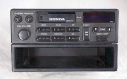
1. The radio from a 1992 Honda Accord. The package tray below it could have been replaced with an optional CD player or equalizer.
Four years ago, the radio really broke. It would not play at all; worse yet, there would be loud RF squealing in the speakers, even with the radio turned off. I assumed this was from a blown output section that was receiving electromagnetic interference (EMI), which the blown transistors would rectify and detect. What I was hearing was the envelope of some cell-phone RF signal. I ripped out the radio and put in an aftermarket Android radio with GPS.
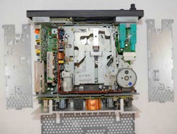
The front speakers went out, so I had replaced all four speakers. All of the foam surround on the speaker cones had disintegrated with age. I wondered if the impedance change caused by this could have affected the radio output stage. I should have known better. As analog aficionado Alan Martin taught me, “It’s always a capacitor.” Analog guru Paul Grohe at Texas Instruments worked on fixing electronics during college. He told me that consumer electronics often have leaky electrolytic capacitors that can do further damage by corroding the printed circuit boards (PCBs). It was time for a teardown (Fig. 2).
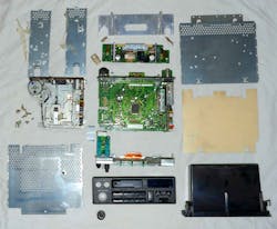
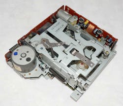
2. The Honda radio tears down into modular sub-assembly. The main PCB is in the center. The output section is above it, and the display section and front panel are below. The cassette player is to the left, and to the right is a plastic shield that keeps the main PCB from shorting to the bottom of the case, here positioned above the shield. The output section has an aluminum heatsink at top center. The screws that hold the transistors to the heatsink have lock-washers, a typical Honda quality touch.
The Label Tells a Tale
The label on the radio was wonderfully informative (Fig. 3). It noted the radio was for a 12-V vehicle with a negative ground. It stated the radio could drive speakers with an impedance of 4 to 8 Ω. Proudly made in Japan, it oddly had the two sides printed upside down. The label also gave a connection diagram for the radio, as well as explaining that if you didn’t have a CD player or equalizer option, you needed a little shorting plug in the DIN socket on the back panel.
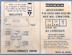
3. The label from a 1992 Honda radio gives both a model number and serial number. It also provides a connection guide.
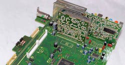
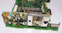
The bottom of the radio was exposed after removing a few Phillips-head screws (Fig. 4). The main circuit board was more complicated than I expected. There are SOT-23 transistors and surface-mount resistors on the bottom of the board. It’s likely Honda glued these to the PCB, assembled the top-side components, and then ran the PCB through a wave-solder machine. The output section had a nice aluminum heatsink for the output transistors. I could see a coupling transformer in the output stage. Honda is remarkable, the company really did not spare any expense.
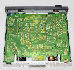
4. The bottom of the radio has a large main PCB with components on both sides.
The panel over the top of the radio was secured to the side panels with clear tape and snap-in sections pressed into the sheet metal (Fig. 5). The cassette player takes a significant amount of space inside the radio. I had bought one of those adapters that went into the cassette slot and took the output from an MP3 player. The unit would send the audio signal to the read-head of the cassette player, and it worked surprisingly well.
5. The top of the radio reveals the solid modular construction.
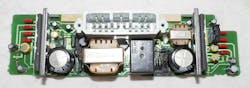
The output section was a well-designed module (Fig. 6). The output section is connected to the main PCB via two single-row headers. It’s a great design for high-volume products. Now you can test the output section as a separate sub-assembly. This improves the chance that the radio will function at final assembly. Note the sheet-metal panel on the main board right above the output section. The screws that hold this to the main board are soldered over to ensure a good RF connection. This gives shielding from ignition and other electromagnetic noise (EMI).
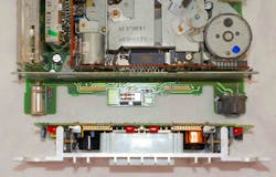
6. The output section, here flipped left-to-right, plugs into the main board with two single-row headers. The antenna connection is on the left, and a mini-DIN connector on the right is used to connect to an optional CD player or equalizer mounted in place of the package tray.
The Problem Reveals Itself
It's always a capactior (Fig. 7). Once I looked at the backside of the output PCB, it was obvious there were leaking electrolytic capacitors. This is what created all of the weird behavior, like a squealing noise even when the radio was off. Flipping the PCB over (Fig. 8), you can see a swollen coupling capacitor on the left; the other one was leaking as well. Note the relay to connect the speakers after all of the electronics stabilize, just like an expensive home stereo.
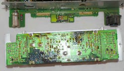
7. The back of the output-section PCB shows evidence of leaky electrolytic capacitors.
8. The front of the output section has a swollen capacitor on the left with obvious PCB damage around both large capacitors.
The front-panel PCB was well-designed and expensive (Fig. 9). Honda engineers used discrete tact switches rather than trying to cheap out with conductive carbon pressing directly on the PCB. The tone controls and speaker balance knobs are on the top left. The buttons click in flush if you’re not using them. If you press them, they pop out, like the one on the right. This lets you adjust the center knob and the collar. It’s a safety feature in case a body part hits the radio in an accident.
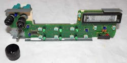
9. The front-panel PCB locates the display, knobs, and buttons. It has blue, green, and yellow LEDs along with tact switches with green buttons. The display is a vacuum-fluorescent type.
The front panel actually has English words—well, abbreviations—to let you know the functions of these knobs. There are green LEDs for functions, and blue LEDs for backlighting. The screen is a blue vacuum-fluorescent unit. These are very good over wide temperature ranges, as in an automobile environment. I never did see why the display was intermittent. It could be the ribbon cable, or it could be solder joints on the PCB itself.
The back of the front-panel PCB has a stout metal support structure (Fig. 10). This is commensurate with Honda quality. You don’t feel any flex when using the radio controls. There’s a main Kapton ribbon cable in the center, and a white ribbon cable connects the two upper knobs to the main board. The volume knob underneath has a PCB with a header that plugs into the main board. The metal structure mounts the cassette player and ties into the side panels. The hole in the structure over the IC may be to help dissipate heat. There are large solder pads on the four corners of the IC to take heat out of the leadframe.
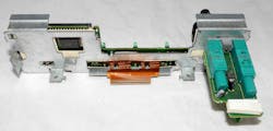
10. The backside of the front-panel PCB is supported by a strong sheet-metal structure.
The backside of the front panel is a mechanical delight (Fig. 11). There are a lot of clear acrylic plastic light pipes that distribute the function and backlight LED lighting. The cassette door was precisely hinged and has a torsion spring to keep it closed. The display is covered by a blue plastic sheet that passes the blue light from the vacuum florescent display, but it blocks the green function LED lighting.
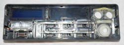
11. The backside of the front panel incorporates clear plastic light pipes to distribute the LED lighting.
The Mechanical Bits
The cassette player is of cheaper construction (Fig. 12). It has single-sided paper-phenolic circuit boards. It’s a purchased part, perhaps from Sanyo or JVC or some other home electronics maker. The entire radio could have been assembled by an outside vendor to Honda specifications. Thing is, Honda really believed in kanban manufacturing principles, so they may have designed and assembled the radios themselves. When Honda builds a factory in the USA, they always try to locate the vendors close to the factory, according to kanban design, rather than just do final assembly of parts sent from Japan.
12. The cassette player is a purchased part with inexpensive circuit boards.
The RF section of the radio was a nice electromechanical assembly (Fig. 13). It’s situated directly in front of the antenna connection. The tuner can may also be a purchased part. It’s amazing Silicon Labs and others can put an entire tuner into a single chip these days—no coils or alignment needed.
13. The RF section of the main board has metal shielding and the many adjustments needed to align the RF tuners.
Complex but Well-Built
I have had several friends tell me it’s never worth working on car radios, they are all too complex and twisted up inside. This was certainly true of a Blaupunkt radio I tore into decades ago.
In contrast, this Honda radio has good modular construction. It’s conceivable that replacing the output capacitors and cleaning the PCB might be all that’s needed to fix it, along with re-seating the display ribbon cable. Nevertheless, this is pretty complex construction. It was obviously styled and then tossed to the engineers to make it work. If we had any say, there would be one PCB for the front panel and one for the main PCB, which would also have the output stage on it. Instead, there are a dozen little subsystems that all could cause quality problems. It’s nice to see how integrated and simple modern radios have become.

About the Author

Paul Rako
Creative Director
Paul Rako is a creative director for Rako Studios. After attending GMI (now Kettering University) and the University of Michigan, he worked as an auto engineer in Detroit. He moved to Silicon Valley to start an engineering consulting company. After his share of startups and contract work, he became an apps engineer at National Semiconductor and a marketing maven at Analog Devices and Atmel. He also had a five-year stint at EDN magazine on the analog beat. His interests include politics, philosophy, motorcycles, and making music and videos. He has six Harley Sportsters, a studio full of musical instruments, a complete laboratory, and a video set at Tranquility Base, his home office in Sun City Center Florida.
Comment About the Article
To join the conversation, and become an exclusive member of Electronic Design, create an account today!

Leaders relevant to this article: