What You'll Learn
- What applications can best use chopper op amps
- How does chopper stabilization work
- What differentiates chopper-stabilized amplifiers from various suppliers
What is a chopper-stabilized operational amplifier (op amp)?
Chopper-stabilized amps constantly correct low-frequency errors across the inputs of the amplifier. This makes them attractive alternatives to conventional op amps in many industrial, medical, energy, and automotive applications to simplify and accelerate the design process. When designing with chopper-stabilized op amps, you do not need to be concerned about compensating for low-frequency errors such as input offset voltage, input bias current, temperature drift, or pink (1/f) noise. Recent developments in process technologies and circuit design have overcome previous limitations that discouraged their use.
How significant are the offset and noise advantages of the latest chopper- stabilized op amps?
Where you might see 2 mV of offset error in a conventional amp, which might be corrected to 100 µV with internal trim-resistor offset-correction, a chopper- stabilized amp may have a maximum input offset as low as 8 µV. Similarly, accuracy over temperature may be as low as 0.02 µV/°C, across the –40°C to 125°C temperature range, compared to 1.5 µV/°C with no correction, or half that with trim-resistor correction.
What’s the problem with 1/f noise in typical designs?
It’s most often a problem in high-precision industrial, automotive, and medical applications. Typical op-amp 1/f noise is greatest right in the area of the sensor bandwidth, limiting possible analog-todigital converter (ADC) resolution. This dc noise can contribute to noise gain errors, affecting the overall accuracy of the output signal in particular for sensor applications requiring high gain.
What applications can best use chopper op amps?
Chopper op amps are generally used in industrial and instrumentation applications, especially when low operating power is also a requirement. Coupled with a suitable ADC, reliable performance with up to 24-bit precision is achievable. A typical application might be a chopper-stabilized op amp used as a buffer precision voltage (or current) source, as a front-end gain amplifier in a sensor application, or in both roles.
In such an application, the output of the pressure sensing bridge is digitized using a high-precision 24-bit sigma-delta ADC. The challenge for designers is that the differential input of a highend sigma-delta ADC often needs to be buffered to prevent it interfering with the sensor performance.
A chopper-stabilized amp is attractive for use as that buffer because as conventional instrumentation topologies cannot meet the noise, voltage offset (VOS), or drift specs required. Moreover, a voltage reference by itself typically won’t drive a pressure-sensor bridge. Its output must be buffered to guarantee that the active voltage to the bridge sensor is stable over temperature and time.
Some of the latest chopper amps also operate across a wide voltage range (1.65 to 5.5 V) and draw as little as 25 µA of quiescent power, making them attractive for battery-powered instrumentation and handheld medical diagnostic devices, wireless sensors, and energy harvesting applications.
How does chopper stabilization work?
Classical chopper (not chopper-stabilized) amplifiers modulated the input signal with a square wave before it was processed by the main amplifier, and they demodulated the signal at the output. Consequently, the signal transfer function was ideally unchanged, Meanwhile, the low-frequency errors that were introduced by the amplifier, being subject only to one modulation, were transformed into errors at the modulation frequency. Assuming that this was sufficiently high, they could then be filtered out by subsequent stages.
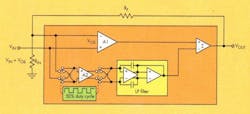
A chopper-stabilized amplifier is actually two amplification paths in parallel (see the figure). A high-accuracy, low-frequency path (A2) incorporates high gain and chopping, while high-frequency signals are amplified by the parallel wideband amplifier A1.
The outputs of both stages are subtracted in a summer amplifier, whose output is fed back to the inputs of both amplifiers through a feedback resistor. In the case of the non-switched wideband amplifier A1, it is fed back to the inverting input in classic gain-setting fashion. In the case of the low-frequency chopped amplifier A2, the feedback signal is connected to one pole of a double-pole, double-throw (DPDT) switch on the die.
The other pole of that switch is connected to the signal input, which is also applied to the non-inverting input of A1. A second DPDT switch on the output of A2 switches its differential outputs synchronously with the front-end DPDT. A low-pass filter circuit gets rid of the high-frequency chopping noise and applies the output of A2 to the summing node. Connecting the inputs of A1 and A2 together allows the chopping in A2 to remove the low-frequency errors from both A1 and A2.
Why the switches?
The switches implement the modulation, causing the input to be multiplied by a square wave at the chopping frequency.
What differentiates chopper-stabilized amplifiers from various suppliers?
The presence of chopping artifacts provides differentiation. The basic ideas of how to remove chopping artifacts such as ripple at the chopping frequency have been around since the days of vacuum tubes, but the current techniques are closely guarded secrets that are constantly being refined.

