Relay-Based ON/OFF Flip-Flop Remembers State During Power Failure
Download this article in PDF format.
Many varieties of ON/OFF control circuits use some form of flip-flop that responds to a pushbutton switch or other control input. These all have volatile memory and default to an OFF condition if power is turned off, and sometimes that's even the preferred situation. However, if your application must remember what it was doing when power failed and resume from where it left off when power is restored, you may have a problem.
Here's a flip-flop circuit that remembers its state indefinitely when power is off. Furthermore, the circuit consumes no power at all, except for a brief instant when triggered from one state to the other. Thus, it’s well-suited to battery power; a couple of lithium coin cells can provide years of battery life.
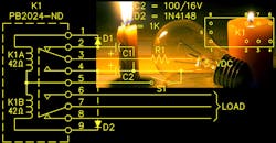
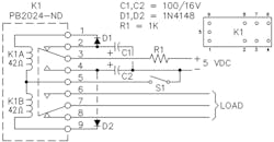
In the design (Fig. 1), K1 is a 5-V dc, dual-coil magnetic latching relay with DPDT contacts. If you search the various distributor offerings, there are about 70 different models of this type relay at coil voltages from 4.5 to 24 V dc, made by four manufacturers, and costing between $3 and $8 in single quantities. They are well built, sealed, very small, and typically have contacts rated for 2 A at up to 250 V ac.
1. This two-coil relay configuration provides a latching flip-flop action without active electronics and retains its state even after power is removed. Component values are not critical.
One set of contacts (pins 2, 3, and 4) are used to steer the flip-flop, and the other set (7, 8, and 9) are available for the end application. In the state shown, C1 has charged to 5 V through R1. Closing S1 discharges C1 through D1 to pulse the K1A coil, transferring the contacts. Then C2 charges through R1 to await the next closure of S1, which discharges C2 through D2 to pulse the K1B coil, returning the contacts to the original state.
This is not a high-speed circuit because of the setup time following a toggle. It was designed primarily for manual input and can toggle at least two times per second. Since power is applied to relay coils only briefly, the circuit tolerates overvoltage without harm, limited primarily by the capacitor voltage rating. When operated at 12 V dc, the circuit shown can toggle as fast as you can tap switch S1. On the other hand, if your application needs to restrict how fast something can be switched on and off, that can be easily limited by increasing the value of R1.
Component values are not very critical. C1 and C2 must store enough energy to pulse the relay, which has an operate time of 20 ms. R1 should be large enough that holding S1 closed does not allow capacitor voltage to rise above 10-20% of relay pull-in voltage.
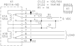
2. This modified version of the original circuit uses a larger center-tapped relay coil with four times the contact-current rating of the two-coil relay approach.
If you need more switching power than 2 A, Figure 2 shows the circuit adapted to a relay that’s four times bulkier and costs twice as much, but has contacts rated for 8 A at 250 V ac. This relay has a center-tapped coil instead of two separate coils, so the pin-out is different and the circuit must be modified slightly.
Tommy Tyler has a degree in mechanical engineering, cum laude, from Vanderbilt University. He retired 22 years ago after a career spanning over 40 years in the design of industrial instrumentation, medical electronics, consumer electronics, and robotics products, earning 17 patents in these fields. In his retirement, he still pursues his hobbies of electronic tinkering as well as technical writing and illustrating.

About the Author
Tommy Tyler 1
Tommy Tyler has a degree in mechanical engineering, cum laude, from Vanderbilt University. He retired 22 years ago after a career spanning over 40 years in the design of industrial instrumentation, medical electronics, consumer electronics, and robotics products, earning 17 patents in these fields. In his retirement, he still pursues his hobbies of electronic tinkering as well as technical writing and illustrating. He can be reached at [email protected].
Comment About the Article
To join the conversation, and become an exclusive member of Electronic Design, create an account today!

Leaders relevant to this article: