
Download this article in PDF format.
With its ever-increasing electronic content, the modern automobile places a premium on energy-efficient design. That’s doubly true for hybrid-electric and full-electric vehicles (HEVs and EVs), in which the battery is the main or only source of power.
Sponsored Resources:
- Integrated Intelligence Part 1: EMI Management
- Integrated Intelligence Part 2: Motor startup open loop acceleration
- Integrated Intelligence Part 3: Motor startup from standstill position
The search for longer battery life has led to the increasing adoption of brushless dc (BLDC) motors over brushed designs. In traditional automobiles with internal combustion engines, BLDCs power accessories such as electric mirrors, fans for ventilation and cooling, and seat motors; in HEVs and EVs, applications expand to include former mechanical and hydraulic functions such as traction motors, generators, AC compressors, water pumps, and power-steering actuators. And let’s not forget two-wheel automotive applications: BLDCs are also making their way into motorcycle and scooter fuel-pump controls.
BLDCs have higher efficiency, higher torque-to-weight ratio, lower maintenance, higher reliability, and lower noise than their brushed motor counterparts. The downside is that they require considerably more electronic circuitry to operate.
A brushed dc motor has a wound armature (rotor) placed between the poles of a magnet
(stator), and uses the brushes to mechanically switch current to the armature and cause it to rotate—a process known as commutation. In contrast, a BLDC has a wound stator with multiple windings that surrounds a permanent-magnet rotor assembly. A controller provides electronic commutation by monitoring the rotor position and supplying power to the stator windings in the correct sequence to start and maintain rotor motion.
Figure 1 compares the drive circuits of a typical brushed and BLDC motor. The brushed motor requires only a single gate driver and power FET. The BLDC motor with its electronic commutation, on the other hand, requires six FETs arranged into three half-bridge pairs, plus a gate driver for each FET and a supervisory device to control the switching order.
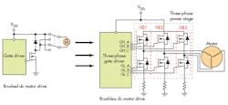
1. The BLDC demands a more complicated drive circuit than the earlier brushed dc motor. (Source: TI Blog: “Demand for higher power density drives innovative power tool solution”)
The simplest control algorithm uses trapezoidal commutation, in which the controller changes the active phases every 60 degrees to maintain rotation. At any time, two of the phases are driven, and the third is disconnected. The current waveform for each active winding follows a trapezoidal waveform, from zero to positive current, then to negative current and back to zero. This sequence adds a ripple to the BLDC torque curve, so trapezoidal commutation is primarily confined to higher speeds and applications where the motor and mechanical linkages will help to reduce the effect.
In low-speed applications, the trapezoidal torque ripple results in uneven operation and acoustic noise. Sinusoidal commutation offers a better approach, as we’ll see.
Overview of Sinusoidal Commutation
The general equation for motor torque is:
T = KT × I × sin(α) (1)
where KT is the torque constant, I is the current through the phase winding, and α is the rotor position in the magnetic field.
For a three-phase BLDC, the motor torque is the sum of the contributions from all three phases. With phase currents IU, IV, and IW:
T = KT [IU sin(α) + IV sin(α +120) + IW sin(α +240)] (2)
The value of T in Equation 2 varies as the rotor spins, leading to torque ripple.
If IU, IV, and IW are sinusoidal with magnitude M and the same phase angles as the above equation:
IU = M × sin(α); IV = M × sin(α +120); IW = M × sin(α +240) (3)
Combining the two equations yields:
T = KT M[ sin2(α) + sin2 (α +120) + sin2 (α +240)] (4)
Naturally, you remember from trigonometry class that:
sin (A+B) = sin (A)cos(B) + (cos(A) sin(B)
and that:
sin2(θ) + cos2(θ) = 1
After much manipulation and substitution of constants, Equation 4 becomes:
T = 1.5 KTM (5)
The torque T now depends only on the motor-torque constant and current magnitude, and is independent of rotor angle. Sinusoidal commutation solves the torque ripple problem.
Sinusoidal Commutation in the Real World: The Phase-to-Phase Method
Pure sinusoidal drive voltages sound great in theory, but are rarely used in practical designs because they’re inefficient to generate for each motor winding with respect to ground. The preferred approach is to generate three sinusoidal voltages between the three phases. This is done by varying the pulse-width-modulation (PWM) duty cycle (and hence drive voltages) relative to ground using the characteristic profile in Figure 2, rather than a pure sinusoid. When any phase is measured with respect to ground, the waveform is sinusoidally coupled with third-order harmonics; the phase current driving the motor follows the pure sine-wave profile of the phase-to-phase voltage.
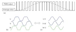
2. The PWM duty cycle (a) generates a characteristic voltage-to-ground profile (b) that results in sinusoidal phase-to-phase voltages and currents (c). (Source: TI “DRV10983-Q1 Automotive, Three-Phase, Sensorless BLDC Motor Driver” PDF, p. 14)
This encoding technique is used in the DRV10983-Q1, discussed below. One phase is held at ground while the other two phases are pulse-width-modulated.
Sensorless Control Lowers Cost
The traditional way to determine rotor position in the BLDC control system is via a sensor, such as a resolver, optical encoder, or Hall-effect device. The first two devices are expensive, but offer high precision; a Hall-effect sensor offers moderate precision at lower cost.
Even an inexpensive sensor, though, increases component count, adds to BOM cost, and is another potential failure source. To reduce cost and size, BLDC control designers have eliminated the position sensor with sinusoidal algorithms that estimate the rotor position using the back electromotive force (BEMF) of the spinning motor.
The BEMF is proportional to motor speed. Sensorless BLDC controllers don’t measure the BEMF directly. Instead, they continuously sample phase current, use this to estimate BEMF voltage, and then determine the rotor speed and position.
Sensorless Startup
The control system must estimate a minimum value of BEMF to accurately estimate the rotor’s position for driving the phases. This presents a problem during startup: At zero speed, there’s no BEMF signal, so the motor is initially driven under open-loop control until its estimated BEMF is high enough to enable closed-loop operation.
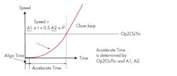
3. The BLDC sensorless startup profile has three parts: stationary rotor position detection; open-loop operation; and closed-loop operation. (Source: TI “DRV10983-Q1 Automotive, Three-Phase, Sensorless BLDC Motor Driver” PDF, p. 28)
The BLDC motor startup in a sensorless system has three elements: first, when the motor is at a standstill; second, when it starts accelerating in open-loop mode without BEMF information; and third, when the BEMF feedback is large enough for closed-loop operation. The sequence is shown in Figure 3. Op2ClsThr is the open- to closed-loop threshold—the speed at which the BEMF is large enough to be useful. The coefficients A1 and A2 set the acceleration rate.
Determining the Initial Rotor Position
If the motor is stationary, the algorithm must first know the position of the rotor so that it can begin driving the phases in the correct order.
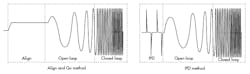
4. IPD and “Align and Go” are two common methods of aligning the BLDC rotor before motion can begin. (Source: TI Blog: “Integrated intelligence part 3: motor startup from standstill position”)
There are two common approaches (Fig. 4). The “Align and Go” method applies a fixed current to one phase, ground to the second, and ground or high-impedance to the third. This forces the rotor magnet to align with the energized coils.
This is a simple approach, but it has two drawbacks. First, the magnitude and duration of the current are motor-specific, so the system must be tuned for each application. Second, the rotor may travel in either the forward or backward direction before settling in its final position; many motor designs don’t allow for backward rotation.
The second method, Initial Position Detection (IPD), uses inductance measurements to determine the rotor position. The driver applies a voltage pulse across each pair of windings in a specific sequence (Fig. 5) and measures the time taken for the current in each of the six pairs to rise to a preset threshold.
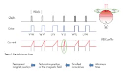
5. The IPD method relies on the relationship between rotor position and inductor saturation. (Source: TI “DRV10983-Q1 Automotive, Three-Phase, Sensorless BLDC Motor Driver” PDF, p. 26)
The current rise time is an indication of the inductance in the motor windings. The inductance measured between a particular pair of windings depends on the rotor position relative to those windings. The shortest time indicates the minimum inductance, which occurs between the two windings most closely aligned with the rotor North pole—phases V and U in Fig. 4.
IPD is faster than align and go, but requires additional hardware; like align and go, it must be tuned for each system. IPD, however, has the advantage of the rotor not moving during position determination.
These startup techniques give the system the specific alignment of the rotor, allowing it to apply the correct driving state to accelerate the rotor in a forward direction.
Open-Loop Operation
During open-loop operation, the motor has no information about the position of the rotor. This phase of open-loop commutation, also known as blind commutation, is very important because it’s directly related to system reliability. If blind commutation isn’t configured correctly, the motor will start, lose synchronization, and stall.
It’s critical that during the open-loop state, the driver can accelerate the motor to a speed high enough for accurate BEMF estimation while also supporting a load.
After reaching hand-off speed Op2ClsThr, the driver switches from open- to closed-loop operation. The value of Op2ClsThr varies based on the torque constant KT of the motor. Motors with a higher KT need a lower hand-off speed, and vice versa.
Driver flexibility is important. Highly desirable features include variable speed profiles to support open-loop acceleration, adjustable current to support a variety of loads, and an adjustable hand-off speed. TI’s integrated drivers support different motor configurations using motor-specific values stored in electrically erasable programmable read-only memory (EEPROM) registers.
Practical Implementation of a Sensorless Controller
The primary blocks in a BLDC controller with sensorless commutation are:
- A microcontroller unit (MCU) or similar device to run the sensorless algorithm
- A three-phase half-bridge power stage
- A power-stage gate driver
- A means of accurately estimating the BEMF
- A power supply for the MCU and other blocks
There are multiple ways to partition a BLDC controller, each one with associated tradeoffs. A multichip design with separate blocks allows each function to be optimized for the highest overall performance, but also has the highest cost, the highest part count, and longest design time. Conversely, a single-chip approach minimizes design time and parts count, as well as reduces cost—but it also limits design flexibility. Figure 6 shows the internal blocks of a typical single-chip intelligent BLDC controller.
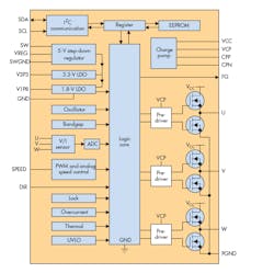
6. An integrated BLDC driver such as the DRV10983 includes control logic, power FETs and drivers, plus protection and communication blocks. (Source: TI DRV10983-Q1 product page)
Texas Instruments offers several intelligent BLDC controllers suitable for automotive applications. The DRV10983-Q1, for example, is a three-phase sensorless motor driver with sinusoidal commutation (Fig. 7). It includes integrated power MOSFETs that can provide continuous drive current up to 2 A.
The device can be configured via an industry-standard I2C interface to accommodate different motor parameters and profiles, and features extensive protection and fault-detection features to ensure reliable operation.
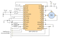
7. The DRV10983-Q1 provides single-chip sensorless control with sinusoidal commutation and either digital or analog control. (Source: TI “DRV10983-Q1 Automotive, Three-Phase, Sensorless BLDC Motor Driver” PDF, p. 1)
The commutation control algorithm continuously measures the motor phase current and periodically measures the VCC supply voltage. The device uses this information to estimate the value of BEMF, and makes it available over an industry-standard I2C interface for external use.
A buck switching regulator efficiently steps down the supply voltage to power both the internal circuitry and external devices such as a microcontroller. If external power isn’t needed, the buck switching regulator can be configured as a linear regulator to save cost.
The DRV10983-Q1 can support both analog and digital control inputs. In addition to digital control via I2C, it includes direction control (DIR) and speed command (SPEED) inputs, plus a speed indicator output (FG).
The device also integrates EEPROM memory for preloaded motor parameters and operation settings. The registers are loaded with EEPROM data on power-on or following an exit from sleep mode. An external microcontroller can dynamically update the motor parameters and operational settings by writing directly to the registers via I2C, bypassing the EEPROM data.
The DRV10983-Q1 is suitable for many low-cost automotive applications. It meets the stringent AEC-Q100 qualification standards, as well as specialized automotive requirements such as the ability to handle a load dump of up to 45 V.
The DRV10983Q1 evaluation module (EVM) offers a convenient way to evaluate the DRV10983-Q1 and TI’s sensorless control algorithm.
Conclusion
Single-chip BLDC drivers are gaining traction (excuse us) in the competitive automotive market due to their low cost, superior performance compared to brushed motors, and sensorless operation. Texas Instruments offers a portfolio of intelligent BLDC drivers for a wide range of automotive and other applications.
Sponsored Resources:
About the Author
Paul Pickering
Paul Pickering has over 35 years of engineering and marketing experience, including stints in automotive electronics, precision analog, power semiconductors, flight simulation and robotics. Originally from the North-East of England, he has lived and worked in Europe, the US, and Japan. He has a B.Sc. (Hons) in Physics & Electronics from Royal Holloway College, University of London, and has done graduate work at Tulsa University. In his spare time, he plays and teaches the guitar in the Phoenix, Ariz. area
Comment About the Article
To join the conversation, and become an exclusive member of Electronic Design, create an account today!

Leaders relevant to this article: