This article is part of the Analog Series: Back to Basics: Impedance Matching
During impedance matching, a specific electronic load (RL) is made to match a generator output impedance (Rg) for maximum power transfer. The need arises in virtually all electronic circuits, especially in RF circuit design.
“Back to Basics: Impedance Matching (Part 1)” discusses the use of a transformer as a basic way to match impedance. This article will introduce the L-network, which is a simple inductor-capacitor (LC) circuit that can be used to match a wide range of impedances in RF circuits.
L-Network Applications And Configurations
The primary applications of L-networks involve impedance matching in RF circuits, transmitters, and receivers. L-networks are useful in matching one amplifier output to the input of a following stage. Another use is matching an antenna impedance to a transmitter output or a receiver input. Any RF circuit application covering a narrow frequency range is a candidate for an L-network.
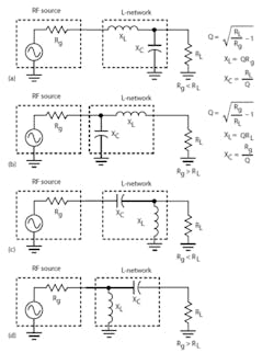
There are four basic versions of the L-network, with two low-pass versions and two high-pass versions (Fig. 1). The low-pass versions are probably the most widely used since they attenuate harmonics, noise, and other undesired signals, as is usually necessary in RF designs. The key design criteria are the magnitudes and relative sizes of the driving generator output impedance and load impedance.
The impedances that are being matched determine the Q of the circuit, which cannot be specified or controlled. If it is essential to control Q and bandwidth, a T or p-network is a better choice. These choices will be covered in a subsequent article.
While the L-network is very versatile, it may not fit every need. There are limits to the range of impedances that it can match. In some instances, the calculated values of inductance or capacitance may be too large or small to be practical for a given frequency range. This problem can sometimes be overcome by switching from a low-pass version to a high-pass version or vice versa.
Design Example #1
The goal is to match the output impedance of a low-power RF transistor amplifier to a 50-output load, and 50 Ω is a universal standard for most receiver, transmitter, and RF circuits. Most power amplifiers have a low output impedance, typically less than 50 Ω .
Figure 2 shows the desired circuit. Assume an amplifier output (generator) impedance of 10 Ω at a frequency of 76 MHz. Calculate the needed inductor and capacitor values using the formulas given in Figure 1a:
Q = v [(RL/Rg) – 1]
Q = v [(50/10) – 1] = v [(5) – 1] = v4 = 2
XL = QRg = 2(10) = 20 Ω
L = XL/2pf
L = 20/[2(3.14)(76 x 10^6)]
L = 42 nH
XC = RL/Q
XC = 50/2 = 25 Ω
C = 1/2pfXC
C = 1/[2(3.14)(76 x 10^6)(25)]
C = 83.8 pF
This solution omits any output impedance reactance such as transistor amplifier output capacitance or inductance and any load reactance that could be shunt capacitance or series inductance. When these factors are known, the computed values can be compensated.
The bandwidth (BW) of the circuit is relatively wide given the low Q of 2:
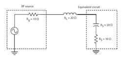
BW = f/Q = 76 x 10^6/2 = 38 x 10^6 = 38 MHzYou can see how this matching network functions by converting the parallel combination of the 50-Ω resistive load and the 25-Ω capacitive reactance into its series equivalent (Fig. 3):
Rs = Rp/(Q^2 + 1)

Rs = 50/(2^2 + 1) = 10 Ω

Xs = Xp/[(Q^2 + 1) Q^2]

Xs = 25/(5/4) = 25/1.25 = 20 Ω
Note how the series equivalent capacitive reactance equals and cancels the series inductive reactance. Also the series equivalent load of 10 Ω matches the generator resistance for maximum power transfer.
Parallel and Series Circuit Equivalents
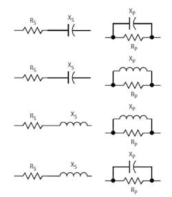
Sometimes it’s necessary to convert a series RC or RL circuit into an equivalent parallel RC or RL circuit or vice versa. Such conversions are useful in RLC circuit analysis and design (Fig. 4).
These equivalents also can help explain how the L-networks and other impedance-matching circuits work. The designations are:
Rs = series resistance

Rp = parallel resistance

Xs = series reactance

Xp = parallel reactance

The conversion formulas are:

Rs = Rp/(Q^2 + 1)

Xs = Xp/[Q^2 + 1)Q^2]

Rp = Rs (Q^2 + 1)

Xp = Xs [(Q^2 +1)/Q^2]

Q = v [Rp/(Rs – 1)]

Q = XL/Rs

Q = Rp/XC
If the Q is greater than 5, you can use the simplified approximations:
Rp =Q^2Rs

Xp = Xs
Design Example #2
Match the output impedance of 50 Ω from a 433-MHz industrial-scientific-medical (ISM) band transmitter to a 5-Ω loop antenna impedance (Fig. 5).
Q = v [(Rg/RL) – 1]

Q = v [(50/5) – 1] = v [(10) – 1] = v9 = 3

XL = QRL = 3(5) = 15 Ω

L = XL/2pf

L = 15/2(3.14)(433 x 10^6)

L = 5.52 nH

XC = Rg/Q

XC = 50/3 = 16.17 Ω

C = 1/2pfXC

C = 1/2(3.14)(433 x 10^6)(16.67)

C = 22 pF
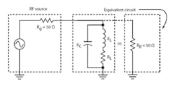
In this example, the capacitor, inductor, and load resistance form a parallel resonant circuit (Fig. 6).
Recall that a parallel resonant circuit acts like an equivalent resistance. That resonant equivalent resistance (RR) of a parallel RLC circuit can be calculated by:
RR = L/CRor:
RR = R(Q^2 +1)

RR = L/CR = 5.52 x 10^–9/(22 x 10^–12)(5) = 50.18 Ω

RR = R(Q^2 +1) = 5(3^2 + 1) = 50 Ω
In both cases the parallel resonant load equivalent resistance is 50 Ω and equal to the generator resistance allowing maximum power transfer. Again, adjustments in these values should be made to include any load reactive component. The equivalent high-pass networks could also be used. One benefit is that the series capacitor can block dc if required.
A Modern Application
In radio communications, a common problem is matching a transmitter, receiver, or transceiver to a given antenna. Most transceivers are designed with a standard 50-Ω input or output impedance. Antenna impedances can vary widely from a few ohms to over a thousand ohms.
To meet the need to match a transceiver to an antenna, the modern antenna tuner has been developed. Manual versions with tunable capacitors and switched tapped inductors have been available for years. Today, modern antenna tuners are automated. When the transceiver is in the transmit mode, the tuner automatically adjusts to ensure the best impedance match possible for maximum power transfer.
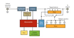
Figure 7 shows a representative tuner. It is essentially an L-network that is adjusted automatically by switching different values of capacitance in or out and/or switching different taps on the inductor to vary the inductance. A microcontroller performs the switching according to some algorithm for impedance matching.
The criterion for determining a correct match is measuring the standing wave ratio (SWR) on the transmission line. The SWR is a measure of the forward and reflected power on a transmission line. If impedances are properly matched, there will be no reflected power and all generated power will be sent to the antenna. The most desirable SWR is 1:1 or 1. Anything higher indicates reflected power and a mismatch. For example, an SWR value of 2 indicates a reflected power of approximately 11%.
In Figure 7, a special SWR sensor circuit measures forward and reflected power and provides proportional dc values to the microcontroller. The microcontroller has internal analog-to-digital converters (ADCs) to provide binary values to the impedance-matching algorithm. Other inputs to the microcontroller are the frequency from a frequency counter circuit and the actual complex load impedance as measured by an impedance-measuring circuit.
One typical commercial automated antenna tuner, the MFJ Enterprises MFJ-928, has an operating frequency range of 1.8 to 30 MHz and can handle RF power up to 200 W. It has an SWR matching range of 8:1 for impedances less than 50 Ω and up to 32:1 for impedances greater than 50 Ω.
The total impedance-matching range is for loads in the 6- to 1600-Ω range. The range of capacitance is 0 to 3900 pF in 256 steps, and the range inductance is 0 to 24 µH in 256 steps. Note that the capacitance may be switched in before or after the inductor. This provides a total of 131,072 different L/C matching combinations.
Such automatic tuners are widely used in amateur radio and the military where multiple antennas on different frequencies may be used. The approach is also used in high-power industrial applications, such as matching the complex impedance of a semiconductor etch chamber in an RF plasma etcher to the 50-O kilowatt power amplifier output. Motors are often used to vary the capacitors and inductors in a closed loop servo feedback system.
Read more of this article that is part of the Analog Series: Back to Basics: Impedance Matching
References
- Automatic L-network calculator
- Frenzel, Louis E. Jr., RF Power for Industrial Applications. Prentice Hall/Pearson, 2004
About the Author

Lou Frenzel
Technical Contributing Editor
Lou Frenzel is a Contributing Technology Editor for Electronic Design Magazine where he writes articles and the blog Communique and other online material on the wireless, networking, and communications sectors. Lou interviews executives and engineers, attends conferences, and researches multiple areas. Lou has been writing in some capacity for ED since 2000.
Lou has 25+ years experience in the electronics industry as an engineer and manager. He has held VP level positions with Heathkit, McGraw Hill, and has 9 years of college teaching experience. Lou holds a bachelor’s degree from the University of Houston and a master’s degree from the University of Maryland. He is author of 28 books on computer and electronic subjects and lives in Bulverde, TX with his wife Joan. His website is www.loufrenzel.com.

