Build A Simple Wireless Bluetooth Stereo Audio System For The Outdoors
Most of today’s portable music comes by way of battery-powered audio devices. Of course, sound systems are available for outdoor use, but they can be quite expensive and, as discussed here, unnecessary. However, with just a bit of engineering blood (or curiosity) running in your veins, it’s relatively easy to construct a wireless Bluetooth stereo audio system that’s controllable with any device incorporating a Bluetooth connection and a music player.
This article describes how to build that wireless Bluetooth stereo audio system—one that’s also fairly low-cost—for outdoor use. The system, which maintains 20-WRMS output power, can be controlled either with a handset containing a Bluetooth connection and a music player or with an Apple iPod model.
Bluetooth technology, created in the late 1990s, is widely used to establish a short-range wireless connection between two handheld mobile devices. A Bluetooth setup also makes it possible to transfer a stereo audio signal from a handheld device to a wireless headset. Today’s Bluetooth headsets operate under the Bluetooth Class 2 specification with 2.5-mW (4 dBm) transmission power. A Bluetooth Class 2 module’s transmission range extends to about 10 meters.
Bluetooth Audio System Assembly
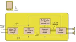
Bluetooth headsets typically employ fairly small, 32-Ω speakers. By connecting the audio signal from a Bluetooth headset to an external amplifier, it’s possible to amplify the signal. The Bluetooth stereo headset then acts as a bridge, delivering the audio signal from the handheld device to a stereo audio amplifier, creating a wireless stereo audio system. This system is based on a stereo Class D audio amplifier, which drives a pair of 4-Ω speakers (Fig. 1).
The output power requirement is 20 WRMS (10 WRMS per channel). Measuring rms output power isn’t the optimal way to determine an amplifier’s output power, since rms doesn’t really reveal much about an amplifier’s true performance. Therefore, in this article, rms output power refers to the average sine-wave power into a resistive load. Consequently, rms output power is used mainly for comparative purposes.
The 20 WRMS translates to 40-W peak output power. To achieve 10-WRMS per channel into 4-Ω speakers, the minimum supply voltage (VRMS) needs to be:
For peak output voltage, this translates to:
Equations 1 and 2 show that a 9-V supply voltage would be enough to achieve 10-WRMS output power per channel. However, this design uses a 12-V supply voltage, which allows some room for the power-supply unit’s (PSU) output voltage to drop during a heavy load.
An isolated PSU with a 12-V output voltage utilizes a low-cost LED driver voltage supply. These supplies are readily available from any electronics store. It’s a matter of choosing a PSU that matches the output power.
As an aside, most people don’t relate to “20-WRMS total output power.” For comparison, think about low-cost car audio amplifiers or low-cost portable audio “boom-box” products. They’re often advertised as providing 40-W total output power, but this is normally peak output power that translates to 20-WRMS output power.
So, then, is 20 WRMS really enough output power for this system to work adequately? Simply, yes. Low-cost car audio amplifiers typically don’t incorporate a step-up dc-dc converter, so they use 12 V from the car’s battery to drive the speakers. (Actually, a car’s battery voltage is about 13.8 V, but that’s not important here.)
Listen to these low-cost amplifiers. They produce plenty of sound. Admittedly, 20-WRMS output power isn’t enough to keep the whole neighborhood awake, but that’s not a priority for this system.
Any headset with a 3.5-mm audio connector will do the trick. This design uses a Nokia BH-214 Bluetooth stereo headset. It has the 3.5-mm audio connector, making it very easy to take audio signals from a headset’s printed-circuit board (PCB) and feed signals to the stereo audio amplifier. An On/Off switch and indicator LEDs are needed as well.
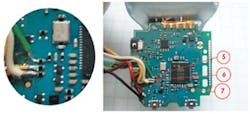
These signals need to be taken from the Nokia headset. Some signals come from outside the Nokia headset’s PCB. As a result, a few wires must be soldered to that PCB to enable signal transmission. Figures 2 to 6 show the procedure.
With the front cover of the headset facing you, open it by gently squeezing with a small screwdriver at the right corners, top and bottom. Remove the plastic faceplate and remove the keyboard rubber. Gently pull the part containing the PCB from the bottom enclosure.
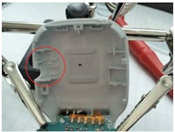
With the front cover open, make some extra room for wires by clipping off some plastic from the area circled in Figure 2. Also remove the light guide and the plastic enclosure for the On/Off switch. Procedures will vary for other headsets.
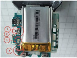
Working from Figure 3, solder off the On/Off-switch (1), the bicolor LED (2), blue LED (3), and battery wires (4). Remove the battery from the PCB.
Now solder wires to the On/Off switch pads (1), as shown by arrows in Figure 3. Then solder a wire to the bicolor LED common anode pad (2), as shown by those arrows. Solder a wire to the blue LED anode pad (3). Finally, solder wires to the battery pads (4). Use the thinnest wires that you can find, and note the wires’ colors for future reference.
Three more wires need to be soldered to the headset (Fig. 4). Solder the green LED cathode (5), red LED cathode (6), and blue LED cathode (7) to resistors (Fig. 4, again). Now there should be wires for the following signals:
- Two wires for the Bluetooth headset’s On/Off switch
- Three wires for the green and red bicolor LEDs (i.e., the common anode, green cathode, and red cathode)
- Two wires for the blue LED (anode and cathode)
- Two wires for the battery terminals (for 3.6 V from the LDO)
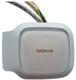
When all wires are soldered to the PCB, gently put the headset back together. Close the enclosure with caution, because it’s very easy to detach a pad from the PCB by pulling the wire. After modifications, the headset will look like that in Figure 5.
Examining The Stereo Audio Amplifier Board
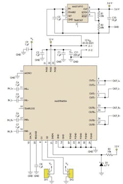
The stereo amplifier used in this design is the MAX98400A Class D amplifier (Fig. 6). An available class AB linear amplifier is an option for this project, but the higher-efficiency Class D amplifier consumes less power and dissipates much less heat. This amplifier exhibits a high 107-dB signal-to-noise ratio (SNR).
Speakers can be connected directly to the amplifier’s outputs without an output filter and without big, bulky dc-blocking capacitors. This latter point is very important. Traditional Class D amplifiers require an output filter to recover the audio signal from the amplifier’s output. The MAX98400A relies on the inherent inductance of speaker coil to recover the audio component of the square-wave output. Thus, eliminating the output filter and dc-blocking capacitors saves considerable space on the PCB.
The stereo audio amplifier incorporates a linear voltage regulator (MAX16910) that converts a 12-V supply to 3.6 V. The LDO output, which can have a voltage between 3.4 V and 4.2 V, connects to the headset’s battery terminals. This device has 30-V (max) input voltage and built-in thermal and overload protection. With the R1 and R2 values given in Figure 6, the LDO’s output voltage will be about 3.8 V.
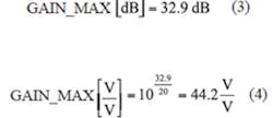
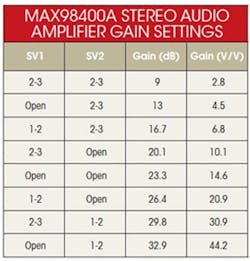
The MAX98400A amplifier needs few external components for its function. Its gain is selected with SV1 and SV2. Gain tops out at 32.9 dB, which equals 44.2 V/V:
Selecting maximum gain occurs when connector SV1 is open and connector SV2 pins 1 and 2 are connected together (see the table). Therefore, with a 12-V supply voltage and 44.2-V/V gain, the maximum input signal that can be used without clipping and distortion to the output signal becomes:
The amplifier contains an integrated clipping-limiter circuit that prevents output clipping distortion. Without that circuit, the headset’s input signal would otherwise need to be adjusted to 270 mV (max) at maximum gain to ensure that the audio amplifier’s output signal isn’t clipped and distorted at maximum volume. Alternatively, the MAX98400A’s gain can be lowered by choosing different settings for SV1 and SV2.
Thermal issues must be considered, too. With a 12-V supply voltage and a 4-Ω load, the amplifier’s efficiency with 20-WRMS output power is about 85%. The power dissipated in the amplifier can be calculated as:
The MAX98400A comes in 36-pin thin quad flat no-lead (TQFN) package, which means it becomes difficult to incorporate an external heatsink. An alternate way to remove excess heat from the amplifier is to connect the exposed pad located underneath it to the PCB’s copper plane with multiple vias.
Moreover, the MAX98400A has built-in thermal overload protection. Consequently, when used in a very warm ambient temperature and with the audio amplifier at its highest possible output power, nothing will be damaged or destroyed in this Bluetooth audio system.
Putting Together The System
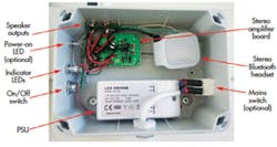
Finally, the system is assembled into an industrial 120- by 160-mm waterproof enclosure. Figure 7 shows the assembled and fully functional system with all required building blocks.
Many different layouts can be employed to assemble the PSU, stereo Bluetooth headset, audio amplifier, switches, and LEDs into an enclosure. Make sure that no cables cross the headset’s Bluetooth antenna, since that can reduce the Bluetooth range.
Also, don’t mount the system very near other wireless transmitters. For example, it shouldn’t be positioned beside a wireless local-area network (WLAN) router, because those transmissions can interfere with the headset’s reception.
The amplifier in this design features a high 67-dB power-supply rejection ratio (PSRR), which eliminates the need for a tightly regulated power supply. Nonetheless, be sure to choose a PSU with reasonably good output-voltage regulation. In practice, that means one should not use the lowest-cost PSU available.
Perhaps the hardest part of building this system involves soldering wires to the LED indicator pads located on the Nokia BH-214 PCB. If you have any doubts about soldering these wires, change to an enclosure with a transparent front cover. Then the stereo Bluetooth headset would be mounted sideways to make indicator LEDs visible through the front cover. Thus, there’s no need to remove the LED indicators from the PCB.
The wires for the On/Off switch and the wires to the battery pads still must be soldered to the headset’s PCB. That’s much easier than soldering for the LED indicators. Also, the power-on LED is optional. If it’s mounted, a series resistor must be used to limit LED current. Calculate the LED series resistor value as:
When the LEDs are supplied from the 3.6-V LDO output and the LED forward voltage equals 1.8 V with, for example, an 8-mA LED current, then the series resistor would be:
Now Make Some Music
This article has explained how to make an inexpensive wireless Bluetooth stereo audio system for outdoor use. Now it’s time to mount the system enclosure on a hard surface (e.g., a wall), connect the speakers, and plug mains voltage into the audio system. Establish a Bluetooth connection and get ready to rock and roll.
