Universal Miniature Transceivers Conquer Industrial Networks

In 2013, RS-485 celebrated its 30th anniversary of transferring from a recommended standard (RS) to an officially supported version, known as EIA/TIA-485. Over these past three decades, RS-485 transceiver designs have evolved from bulky dual inline plastic and ceramic packages to tiny small-outline beads. In addition drastically reducing the footprint, modern transceivers reduce power consumption, increase noise immunity, and substantially increase upper data rates while offering programmable features that make them versatile for a wider range of system designs.
Related Articles
- Energy Harvesting And Wireless Sensor Networks Drive Industrial Applications
- Energy Harvesting Powers Wireless Sensor Networks In Industrial Apps
- Save Power In Building Automation Systems
Functional Principles And Design Benefits
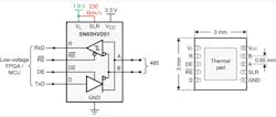
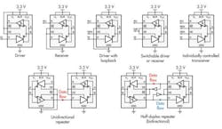
Modern transceiver designs combine versatility with a tiny form factor for a wide variety of industrial, telecommunications, maritime, and building networks (Fig. 1). They comprise two separate power supply inputs: one for logic control functions, and the other for the bus supply. The control supply accepts voltages from as low as 1.65 V minimum up to a maximum of 3.6 V and enables the direct interface to low-voltage FPGAs and microcontrollers. The bus supply, however, requires 3.0 V to 3.6 V to ensure sufficient output drive capability across a wide common-mode range.
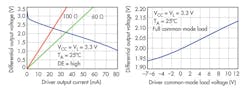
While plenty of low-voltage transceivers are on the market, some of them are down-rated 5-V transceivers that run out of gas at low supply voltage, particularly when operated across a wide common-mode range. A quick check of the transceiver data sheet should convince you that your transceiver complies with RS-485 by providing a minimum differential output voltage of 1.5 V across a differential 54-Ω load while being tested across a common-mode voltage range from –7 V to 12 V. Two output characteristics can prove whether your transceiver meets or exceeds these requirements (Fig. 2).
Selecting Data Rates
To address a wide range of applications, a data rate select-pin, SLR, allows for switching between low and high data rates while providing automatic slew rate adjustments to minimize electromagnetic interference (EMI) with other circuitry. Connecting the SLR pin to the logic supply, VL, sets the transceiver into low-data-rate mode supporting up to 250 kbits/s. Lower data rates with longer rise and fall times are useful in EMI-sensitive applications and in long-distance networks (Fig. 3). Grounding the SLR pin turns allows for data rates of up to 20 Mbits/s at siginificantly shorter bus lengths.
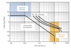
The conventional characteristic can be exceeded through additional signal processing. This can include signal buffering through repeaters and/or signal and clock recovery functions of synchronized or clock-encoded data streams through complex FPGA building blocks and software algorithms.
Long and ultra-long networks typically operate in half-duplex mode between 20 kbits/s and 100 kbits/s and use half-duplex repeaters to cover the long distance. High-speed networks in motor control and seismic applications often cover up to 300 m of bus length at data rates of 5 Mbits/s to 20 Mbits/s. Here, a single data line is either clock-encoded at the driver side and decoded at the receiving end, or a separate clock line is run parallel to one or multiple data lines and propagation-delay compensation is applied at the receiver.
Reusability Through Small Form Factor
To be applicable to many designs, transceivers must be versatile by being configurable for all kinds of operation modes. Three basic topologies are applied in RS-485 networks (Fig. 4):
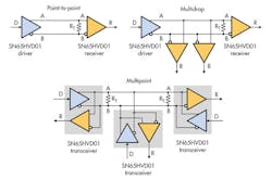
• A point-to-point data link consists of a dedicated driver and one receiver. Because the data flow is unidirectional, a line termination resistor RT, whose value should match the characteristic line impedance Z0, is only required at the receiver.
• The multi-drop topology also utilizes a dedicated driver but has multiple receivers. Again, RT is only required at the receiving bus end. Both topologies allow for the driver and receivers to be either permanently active or selectively disabled.
• The multi-point topology connects multiple transceivers through daisy-chaining to one bus. Only one driver can actively drive the bus at a time. A multi-point bus, therefore, must work in half-duplex mode. That is, any node can either transmit or receive data, but never both at the same time. Because data flow is bidirectional, line termination must be applied to both ends of the bus.
Historically, system designers would choose various driver, receiver, and transceiver components to accomplish the individual device functions. Miniature transceivers, however, enable the configuration of all of the above operation modes within one device (Fig. 5).
The 3- by 3-mm package size enables network functions requiring two transceivers such as repeaters and clock-synchronized transmitters on much smaller board space. Finally, the pin-pitch of 0.65 mm enables worldwide assembly houses to use standard assembly equipment.
Operation Robustness
When operating in harsh industrial environments, transceivers must be able to work reliably across a wide temperature range from –45°C to 125°C. Also, electrostatic discharges (ESD) due to human interference as well as electrical fast transients (EFT) caused by relay bouncing and other inductive load switching can cause latch-up and serious device damage in transceivers without sufficient transient protection. New transceivers can withstand ESD transients according to IEC61000-4-2 of up to ±16 kV and EFT transients according to IEC61000-4-4 of up to ±4 kV without toggling the power supply.
Legacy transceivers with ±200-mV input sensitivity required external failsafe biasing resistors of low resistance to ensure high differential noise immunity during bus-idling states, when no driver was accessing the bus. State-of-the-art transceivers, however, provide internal biasing of the receiver input thresholds in combination with large input-threshold hysteresis.
For example, a transceiver could have a typical positive input threshold of VIT+ = –60 mV and an input hysteresis of VHYS = 70 mV. This defines the negative input threshold with VIT– = VIT+ – VHYS = 60 mV – 70 mV = –130 mV.
So, flipping the receiver output erroneously from high to low requires a differential noise of 130 mVPK. This is an awful lot of noise—roughly three times that of a well-balanced data link. Because the transceiver provides such high immunity, the need for external bias resistors is removed and power consumption is reduced.
Applications
Many high-speed data links using RS-485 transceivers can be found in modern seismic networks, position encoders in drive systems, and communication links between GPS and server cards in telecommunications. Data rates can reach 20 Mbits/s with bus lengths of up to 300 m to cover. Sending high data rates over long distances can increase inter-symbol-interference (ISI), leading to a drastic closure of the eye diagram. To reduce ISI, data is encoded with the clock signal to accomplish more balanced charging and discharging of the cable capacitance.
One commonly applied encoding mechanism is Manchester coding, where the original data is XOR-ed with a clock signal to yield the final transmit data sent by the driver (Fig. 6a). On the receiver side, a rather complex decoding algorithm performs oversampling at six to eight times the initial clock frequency to recover the original clock information before decoding the encoded receive data.
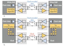
Another transmission method is the run of a separate clock channel parallel to the data channel or channels. The data is still clock-encoded, but the presence of a dedicated clock channel removes the actual clock recovery process (Fig. 6b). On the receiver side multiple versions of the received clock signal are generated, each with a different propagation delay. Every clock version is then used for decoding the incoming receive data. A novel selection algorithm decides which decoded signal provides the most meaningful result.
Long-distance networks operate at data rates from 10 kbits/s to 100 kbits/s and can cover from 5000 feet up to 20 miles (~105,000 feet), clearly exceeding the reach of conventional RS-485 networks. To prevent data errors due to large ground potential differences along the link, all bus nodes are galvanically isolated from their local controller/UART circuits (Fig. 7).
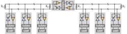
Line termination in combination with failsafe biasing is usually applied to both bus ends to ensure a well-balanced bus immune to common-mode and differential noise. While a single bus segment can reach up to one mile (5300 feet), longer distances are achieved through the use of half-duplex repeaters between segments.
Conclusion
Miniature RS-485 transceivers conquer a wide range of network applications. The combination of switchable data rates and long-distance drive capability at low supply voltage makes them the most versatile components in the industry. Texas Instruments entertains a huge portfolio of RS-485 transceivers in varying package sizes with features including integrated lighting protection, receiver high-pass filters, large input hysteresis, and cross-wire fault compensation.
This file type includes high resolution graphics and schematics when applicable.
References
For more information visit www.ti.com/rs485-ca.
Download this datasheet: www.ti.com/sn65hvd01-ca.
Thomas Kugelstadt is an applications manager with Texas Instruments. He is responsible for defining new, high-performance analog products and developing complete system solutions for industrial interfaces with robust transient protection. He is a graduate engineer from the Frankfurt University of Applied Science. He can be reached at [email protected].
About the Author
Thomas Kugelstadt
Thomas Kugelstadt is a senior systems engineer with Texas Instruments. He is responsible for defining new, high-performance analog products and developing complete system solutions that detect and condition low-level analog signals in industrial systems. He is a Graduate Engineer from the Frankfurt University of Applied Science.
Comment About the Article
To join the conversation, and become an exclusive member of Electronic Design, create an account today!

Leaders relevant to this article: