What’s The Difference Between Cable And DSL Broadband Access?
Download this article in PDF format.
Most people use cable TV or digital subscriber line (DSL) for high-speed Internet access at home. In fact, 50% of all broadband customers use cable, 42% use DSL, and 8% use fiber-optic cable, satellite, or a wireless system. However, DSL dominates in Europe and the rest of the world. Cable and DSL both have been around for years with steady upgrades and improvements, though their methods for delivering high-speed data are very different.
Cable TV Systems
Cable TV systems were developed to provide reliable TV service to local communities. Along with the hundreds of TV channels available, cable companies offer services such as high-speed Internet access. Some even offer voice over IP (VoIP) telephone service. Cable companies usually offer a “triple-play” package that bundles TV, phone, and Internet services.
Systems have been upgraded from pure analog transmission to digital. Early systems were based on coax cable, but today the most common configuration is fiber-optic cable and coax. Hybrid fiber coax is one of the most common configurations (Fig. 1).
1. The typical hybrid fiber coax (HFC) cable TV distribution system used throughout the U.S. consists of fiber-optic cable to neighborhood nodes that then distribute the signals to homes with RG-6/U coax.
All of the services originate from the cable company’s facilities, known as the headend, where the company collects the video from local TV stations and cable TV programming suppliers via satellite. The company then packages multiple channels into bundles for basic cable as well as two or three other options of premium movie and/or sports channels. The headend also has an interconnection to the Internet, where it can supply Internet services or connect to a separate Internet service provider.
The headend connects to the end user via a network of fiber-optic and coax cables. The TV channels and Internet channels are frequency multiplexed and modulated on to the main fiber-optic cable for transport out to distribution hubs that rejuvenate the signals over longer cable runs. From the one or more distribution hubs, the signal travels to multiple optical nodes located in various city or suburban neighborhoods. In a typical configuration, a single fiber is split to serve four fiber optical nodes. Most fiber nodes serve up to 500 homes. With this arrangement, each fiber serves up to 2000 homes, although not all homes passed have a cable modem or service.
The optical nodes convert the optical signals into electrical signals for the final distribution via coax cable. The most common cable is RG-6/U 75-ohm coax using F-type connectors. All of the homes receive the same signal, just like a bus network topology. In some areas with longer distances, amplifiers are added along the way to mitigate the large cable losses that are common.
All of the TV signals and Internet data are transmitted in a spectrum of 6-MHz wide channels. Since a coax cable has a bandwidth as wide as 850 MHz to 1 GHz, the system can accommodate from 140 to 170 downstream channels of 6 MHz each. The TV signals or Internet data are modulated on to carriers in each channel. There are also upstream channels that allow the consumer to transmit data back to the headend. This communication takes places in 6-MHz channels as well that occupy the cable spectrum from 5 MHz to 40 MHz or in some systems up to 65 MHz.
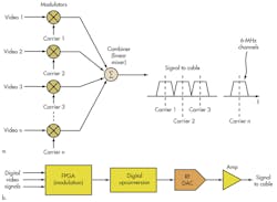
The composite video signal is developed in equipment called the cable modem termination system (CMTS). In older systems, the video information is modulated on to the 6-MHz channel carriers and then all channels are combined or linearly mixed to form the composited cable signal (Fig. 2a). However, today it’s possible to synthesize a full block of modulated channels digitally. The digitized video is sent to an ASIC or FPGA programmed to produce the desired quadrature amplitude modulation (QAM) for each channel (Fig. 2b). The signals are then digitally upconverted to the final frequency and sent to a wideband digital-to-analog converter (DAC) that produces the composite multi-channel signal to be sent to the cable.
2. In older cable TV systems, individual modulators add the video to the channel carriers that are linearly mixed to form the composite signal for transmission over the cable (a). Modern cable TV systems are beginning to use direct digital synthesis of the composite signal for transmission (b). The digital video signals are fed to an ASIC or FPGA, where an inverse FFT and other techniques implement the QAM modulation and upconversion. A fast RF DAC develops the final composite analog signal for transmission on the cable.
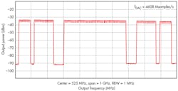
Maxim Integrated’s MAX5880 modulator/digital upconverter (DUC) can generate from eight to 128 QAM modulated channels. It is a 14-bit RF DAC with a 4.6-Gsample/s rate that produces the final signal. Figure 3 shows what the output signal looks like in the frequency domain.
3. This illustration shows a spectrum analyzer output display of 128 QAM channels generated by the MAX5882 and MAX5880 combination. The full bandwidth is 1 GHz with a center frequency of 525 MHz. The resolution bandwidth is 1 MHz. You can just make out the 6-MHz channels, 16 per 100-MHz segment.
In older analog systems, each TV signal occupied one 6-MHz channel. Modern digital signals may have one TV signal per channel or more. Digital TV signals can be compressed using MPEG compression algorithms to reduce the amount of channel space required for transmission, allowing multiple signals per channel. Downstream modulation is usually 64-state QAM (64QAM) or 256-state QAM (256QAM), meaning each channel can deliver a data rate up to 38 Mbits/s. Higher speeds can be achieved by using channel bonding, which transmits the data stream in two or more 6-MHz channels.
Users do not usually get the full download speeds mentioned above. Because the coax line is a bus shared by many homes, the data speed is divided up amongst those who are using the connection. A single user will get the full speed but with multiple users each will get a proportionally slower connection.
Upstream modulation is quadrature phase-shift keying (QPSK) or one of several variations of 16/32/64/128QAM. Upstream rates are typically less than 27 Mbits/s.
The downstream data is routed through the cable wiring in the home through splitters that divide the signal for multiple room connections. One or two devices then recover the signals. A cable box or set-top box (STB) selects the desired television channel with a tuner and directs the signals to the TV set for presentation. In some cases, a cable-ready TV can recover the signals without the STB.
Internet service and VoIP telephone service use a cable modem, which connects to the Ethernet port on a PC or laptop. In many homes today the cable modem connects to a wireless router that distributes the service by Wi-Fi to PCs, laptops, tablets, or cell phones.
Most cable modems also have a telephone option where the digital VoIP is converted to be compatible with the standard telephone wiring in the home so standard phones can be used. A standard RJ-11 connector connects the cable modem to the home wiring.
Most cable systems are based on the Data Over Cable Service Interface Specification (DOCSIS). Developed by CableLabs in cooperation with the industry, DOCSIS defines the operating system and the hardware specifications. Version 1.0 was introduced in 1997. DOCSIS 2.0 came along in 2001, and DOCSIS 3.0 was released in 2006. Most systems use the latest version, which is IPv6 capable. DOCSIS also provides multiple security options including a Baseline Privacy Interface (BPI) or security (SEC) option. The 56-bit DES and AES 128 encryption methods are available, as is public key infrastructure (PKI) authentication.
DSL
DSL is one of the oldest forms of high-speed Internet access. It had its start in the 1990s and has since evolved into a very stable and capable platform. It uses existing telephone wiring, generally known as the plain old telephone system (POTS). The in-place unshielded twisted pair (UTP) telephone lines form the backbone of the legacy wired telephone system. Thanks to technological developments, this wiring that was installed to handle voice telephone calls can now deliver high-speed digital data at 50-Mbit/s rates and beyond in some cases.
In a typical system, the telephone central office is connected to each subscriber by one or more #24 or #26 copper wire unshielded twisted pairs, with one for each telephone number. The lines are not shared. The cable runs vary from a few hundred feet to a maximum of 9000 to 18,000 feet (2.7 to 5.5 km). The system was designed to carry voice in the 0- to 4-kHz range. Early in the Internet era, dialup modems were designed to carry digital data over these analog lines. Special QAM modulation and encoding schemes allowed data to be carried at rates to about 56 kbits/s maximum. Then the DSL system was developed to carry much higher speeds.
The original DSL system was designed to produce data rates of 1.5 Mbits/s to 8 Mbits/s downstream from the telephone company to the subscriber and a lower rate upstream. Most Internet access involves more downloading and less uploading of data. The resulting design is referred to as asymmetrical DSL or ADSL. Most DSL formats are asymmetrical, although there are DSL variations that deliver the same rates in both directions.
The great attenuation, noise, and crosstalk problems of bundling multiple twisted-pair lines are the primary limitations of the POTS. These lines are effectively long low-pass filters with upper frequency limits that reduce the bandwidth of the line and limit the data rate that can be achieved. Line bandwidth is a function of the length of the UTP. Shorter cable runs have wider bandwidths, so they are clearly more capable of high data rates than longer runs. But despite this limitation, developments in digital signal processing have made this once limited communications medium capable of high-speed data delivery.
The telephone companies (telcos) have upgraded this basic system to include neighborhood terminals called digital subscriber line access multiplexers (DSLAMs). The DSLAM shortens the distance from the subscriber to the central office, so much higher speeds can be delivered. For shorter cable runs, the DSLAM may be in the central office. The DSLAM aggregates the data from multiple subscribers and connects them back to the central office by fiber-optic cables. This arrangement is generally known as fiber to the node (FTTN). Older systems used T1 or T3 lines, but today most DSLAM connections are fiber.
On the consumer end of the telephone line is a DSL modem generally called the customer premise equipment (CPE) that is used to demodulate the signals from the DSLAM and modulate any upstream transmissions. A low-pass filter separates the 0- to 4-kHz voice spectrum from the higher frequencies used for data transmission.
Most DSL systems use a modulation scheme similar to orthogonal frequency division multiplexing (OFDM) called discrete multitone (DMT). It divides the cable spectrum into subchannels or bins that are 4.3125 kHz wide (Fig. 4). The original basic DSL uses 256 subchannels for a bandwidth of 1.1 MHz. The lower subchannels from approximately 26 kHz to 138 kHz are used for upstream transmissions from the subscriber to the central office. Above 138 kHz to about 1.1 MHz are the subchannels used for downstream transmission.
4. This is the spectrum of the unshielded twisted-pair cable showing the subcarriers and the upstream and downstream allocations for ADSL, ADSL2, VDSL, and VDSL2.
As in OFDM, the high-speed serial data to be transmitted is divided into many slower parallel streams, each of which modulates a subcarrier in each subchannel. Modulation can be from QPSK to 64QAM. In DSL, the maximum bit rate per carrier is 60 kbits/s. The modulation is accomplished digitally in a digital signal processor (DSP) using the inverse fast Fourier transform (IFFT) for modulation and FFT for demodulation.
The actual data rate depends not only on the modulation method used but also on the number of subchannels used—and, of course, the distance between the central office or DSLAM and the CPE. Noise is another limiting factor. The DSLAM and DSL modem can adapt to noise conditions by examining the spectrum and blocking channels with excessive noise content. This reduces the speed but maintains the link with accurate data.
There are many different versions. ADSL is the most common, although some newer and more advanced versions are widely used. For example, ADSL2 extends the line bandwidth to 2.2 MHz and 512 subchannels, extending the maximum data rate to 12 Mbits/s. Another variation, ADSL2+, further extends the maximum rate to 24 Mbits/s.
Then there is video DSL (VDSL). Designed to carry compressed digital video for HDTV, it achieves even higher rates by using more of the cable bandwidth and further restricting its length. There are multiple versions including VDSL2 with a variety of specifications.
One version uses the UTP cable bandwidth out to 8.832 MHz with 2048 subcarriers to achieve a maximum rate of 50 Mbits/s. Other versions use 12, 17, or 30 MHz of bandwidth. With the 17-MHz bandwdith and 4096 subcarriers, the maximum possible data rate is 100 Mbits/s. Another version uses 30 MHz of bandwidth with 3479 subchannels that are 8.625 kHz wide instead of the usual 4.3125 kHz. Maximum data rate is 200 Mbits/s. The range is usually restricted to 1000 to 3000 feet. Unlike cable TV connections, DSL gives the full speed to each user.
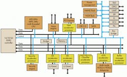
To make VDSL2 even faster, companies like Broadcom, Ikanos, and Lantiq are implementing VDSL2 chips with a feature called vectoring. This digital signal processing technique cancels noise and far-end crosstalk (FEXT) between bundled twisted pairs, enabling high speeds. These new chips also implement channel bonding that permits two twisted pairs to be used simultaneously to further increase speed to 200 Mbits/s downstream and 100 Mbits/s upstream. For example, the Ikanos’ Vx185-HP communications processor chipset implements VDSL2 as well as vectoring and channel bonding in a home gateway (Fig. 5).
5. The Ikanos Fusiv Vx185-HP home gateway chip implements ADSL2 and VDSL2. A MIPS 600-MHz processor is the host. Interfaces include two 1-Gbit/s Ethernet ports, PCI Express, USB 2.0, SATA, and the usual UART, SPI, I2C, and GPIO ports. VoIP processing is included.
AT&T’s popular U-verse system uses VDSL2. It sends video signals by fiber to a neighborhood DSLAM and then distributes the signal to homes over the installed UTP wiring. The U-verse system provides cable TV-like service with IPTV as well as VoIP and Internet access.
The International Telecommunications Union-Telecommunications (ITU-T) standardizes DSL specifications. The ADSL standard is G.991 and G.992. The ADSL2 standard is G.993 and G.994. ADSL2+ is specified in G.995. The standards G.993.1 and G.992 define VDSL and VDSL2. The vectoring standard is G.993-5, and the channel bonding standard is G.998.1.
Alternate Systems
Most consumers use cable TV or DSL for Internet service. However, there are instances where other methods are desirable or necessary. In many areas where new homes are being built, installing fiber-optic cable directly to the home (FTTH) is no more expensive. For example, Verizon’s FIOS system isn’t widely available but does provide services with typical rates from 50 to 100 Mbits/s.
Some rural systems use wireless methods. Clearwire’s system uses the WiMAX standard (IEEE 802.16) to deliver data rates from 1 to 5 Mbits/s over several miles. For even more remote service, a few companies offer satellite downstream data at rates to several megabits per second.
References
Broadband Forum: www.broadband-forum.org
CableLabs: www.cablelabs.com
About the Author

Lou Frenzel
Technical Contributing Editor
Lou Frenzel is a Contributing Technology Editor for Electronic Design Magazine where he writes articles and the blog Communique and other online material on the wireless, networking, and communications sectors. Lou interviews executives and engineers, attends conferences, and researches multiple areas. Lou has been writing in some capacity for ED since 2000.
Lou has 25+ years experience in the electronics industry as an engineer and manager. He has held VP level positions with Heathkit, McGraw Hill, and has 9 years of college teaching experience. Lou holds a bachelor’s degree from the University of Houston and a master’s degree from the University of Maryland. He is author of 28 books on computer and electronic subjects and lives in Bulverde, TX with his wife Joan. His website is www.loufrenzel.com.


