Under Review: EAGLE and DipTrace PCB Design Tools for 3D Previews
This file type includes high-resolution graphics and schematics when applicable.
This article takes a look at how to get a 3D preview of a printed-circuit-board (PCB) project designed using mid-level PCB design tools, such as EAGLE and DipTrace. It also discusses how to integrate these EDA systems with mechanical CAD software. I will try to describe both software packages “as is,” and avoid any conclusions.
The ability to see the real-life model of a PCB in 3D allows the designer to avoid mistakes. Moreover, it provides vital production integration when a board’s model is saved in the common MCAD data-exchange format—STEP (Standard for Data Exchange of Product Data).
We exclude tools from Mentor Graphics, Cadence, and Altium because of their cost. Freeware programs with 3D, such as DesignSpark and KiCAD, are way too basic and lack 3D STEP export, so that leaves us with DipTrace, EAGLE, maybe Target 3001, or Easy-PC. Let's talk about the first two.
DipTrace
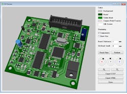
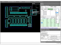
This EDA/CAD software has a built-in real-time 3D preview module with STEP and VRML export capabilities out of the box. The 3D Preview module is somewhat similar to the Altium’s 3D, but a little more basic without single-layer display modes and cross-sectional views. DipTrace exports a 3D board model with all components installed into the STEP file, just like Altium Designer. This provides reasonably hassle-free integration with MCAD packages. VRML exporting is great for demonstration, but I've found it rarely used for any practical engineering tasks.
DipTrace comes with a standard 3D model library, which developers offer for free. Usually, a component footprint is linked with a 3D model. If not, then program automatically searches the standard library when launching a 3D preview; users can adjust the search tolerance settings and search folders.
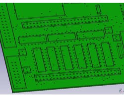
However, the standard library itself is not that big, which is why I often end up with blank footprints on the board in 3D. Notice that you can not specify the height of the footprint directly in DipTrace (like I used to do when dealing with blank footprints in Altium) to generate a simple square or rectangle shape for rough-estimate visualization. This is why, sometimes, I would sacrifice precision and details when feeling lazy, and instead use the models of the similar footprints (since DipTrace allows you to pick up any model from the library and scale it while mapping).
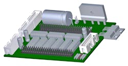
But that was before I discovered that I can attach an external STEP file as the component model. Since STEP models can be easily downloaded from manufacturer websites, this doesn’t seem to be an issue anymore. The software also supports IGES, 3DS, and VRML models.
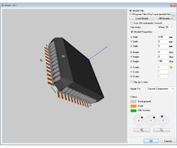
Mapping the component to the footprint is pretty straightforward (enter appropriate parameters into the corresponding fields). A 3D model (above) is locked to the footprint; you won't need to attach and map it again in the future.
EAGLE
EAGLE does not have any built-in 3D preview capabilities. However, the "Feathery" has a bunch of user language programs (ULPs). CadSoft officially promotes three ways to 3D visualize and export boards:
• Eagle’up
• IDF export
• IDF-to-3D
EAGLE’up
You need to download and install the following: SketchUp software; eagleUP (user language program for EAGLE); a special plug-in for SketchUp (*.rbz file); and ImageMagick (open-source raster-to-vector software suit).
All component models should be manually attached to the board model in SketchUp. You can’t use STEP or IGES models from manufacturer's websites. You will likely end up building models by yourself.
SketchUp full-version costs reasonable money, but it doesn't export STEP files. You may need some additional plug-ins, which are rare and costly.
IDF export
Starting from version 7, EAGLE incorporates IDF export capabilities based on another ULP—no additional plug-ins are required. All you need is an MCAD tool with IDF import such as Solidworks, FreeCAD (below), etc.
Launch eagleIDFexporter.ulp and press “Generate IDF Files.” The *.emn and *.emp files will appear. IDF exports the height of the components on the board, a 1-mm value is assigned by default. To change component height in EAGLE, you should assign the “HEIGHT” attribute to each component, or edit the *.emp file with Notepad. Then open MCAD software and import the board model.
Unfortunately, the IDF format does not contain any component 3D models. You will need to design or import models from the Internet and map them manually to the footprints. Sometimes it can take up to a couple hours, depending on the complexity of the project. Do not forget about import/export restrictions of your MCAD software, and its price...
IDF-to-3D
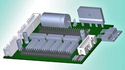
This is based on the IDF-export ULP, but integrates with third-party, browser-based software from Simplified Solutions. IDF-to-3D is an online 3D Preview service that requires a registration. The website accepts an IDF file from EAGLE, provides an extensive library of 3D component models, and allows for STEP model search and uploading. There are sufficient 3D-model mapping tools and 3D PDF or STEP file export for MCAD tools.
A free account at IDF-to-3D allows only for 3D PDF exporting (above). This format is good for demonstration and visualization (only the ubiquitous Adobe Reader is required), but STEP and STL export features are locked, and only for paying customers. Subscription is costly and time-restricted. Not everyone (especially those in charge) is happy with sending valuable projects over the Internet.
Conclusions…well not formal ones
Both EAGLE and DipTrace are pretty affordable with no annual maintenance fee. Both offer a restricted freeware version for hobbyists and the vast engineering communities. We concentrated only on the 3D field, and as I promised, I'm not making any conclusions here—it’s up to you.
Vlad Khomenko, born in Ukraine, studied in the Dnipro National University. He is a freelance technical writer, traveler, PCB designer, and electronics enthusiast.
About the Author
Comment About the Article
To join the conversation, and become an exclusive member of Electronic Design, create an account today!

Leaders relevant to this article: