>> Electronic Design Resources
.. >> Library: Article Series
.. .. >> Series: Ideas for Design
.. .. .. >> Ideas for Design Vol. 1
Download this article as a PDF file
Game-show "contestant-selection" controllers aren't new. But the designs are complicated, especially as the number of inputs grows. This contestant controller is simple and expands easily.
The idea is to keep arbitration to a minimum. In other words, minimize the possibility of two or more contestants getting through the circuit and then having to arbitrate which contestant is selected. The key is to minimize the "window of opportunity" during which two or more signals can pass through the circuit. The smaller the window, the less likely arbitration will be needed.
This design has a window of opportunity so small (nanoseconds) that if two or more signals get through, you can call it a tie. If arbitration is still desired, a microcontroller or scanning multiplexer could continuously scan the output and stop on the first signal it detects.
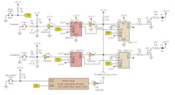
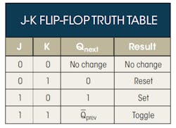
The circuit uses J-K flip-flops to allow one signal through and block the rest, with the J and K inputs allowing the flip-flop to toggle or not (see the figure). The starting state of all flip-flops is CLR. (All Q outputs equal 0.)
This two-input version of the contestant-selection circuit can easily be expanded by adding additional input sections connected in a similar fashion.
Each contestant's input contains a D flip-flop (U1) with the contestant button connected to the positive-edge clock input. Once the button is pressed, the high on the D input is clocked to the output and any further pressing of the button does nothing, effectively disconnecting the button.
The inverter between the D and J-K flip-flops sets the window of opportunity. As an open-drain device, it allows logical ORing with inverters from other contestant inputs and connects to all J inputs of the J-K flip-flops.
U3 inverts the Q output from the D flip-flop and delays it long enough to allow the \\[overbar\\]Q output of the D flip-flop to clock the J-K flip-flop while the J input is still low. Once the delayed Q output passes through the inverter, all the J inputs are taken to 0. At this point, any clock signals on any of the J-K flip-flops will not change the output.
The outputs of the J-K flip-flops can then drive indicators directly or be used as inputs to a microcontroller to ensure one output is selected in the unlikely event that two signals get through. As noted, you could also use a multiplexer (several to one) to count through the outputs, stopping on the first output that is detected high. The count would then reflect the winning contestant.
Resetting the circuit is simply a matter of clearing the flip-flops. A timeout signal can be implemented in two ways: ORing with the output of the open-drain inverters or using an unused contestant input. The timeout circuit can be anything from a button to an RC circuit or some other timing circuit.
Because flip-flops generally come packaged in pairs, the number of inputs would be even. Additionally, the design scales up linearly. Simply add contestant sections connected as the first two are connected. The circuit was built using standard 5-V transistor-transistor logic (TTL) and open-collector inverters. The CMOS version of TTL was not tested but should function similarly.


