6 Industry Trends Reflected in Third DVCon India Technical Program
This file type includes high-resolution graphics and schematics when applicable.
One of the best ways to gauge what new technologies, trends, and product categories are hot in electronics is to look at the technical programs for major industry conferences. Reviewers for submitted papers work hard to ensure that conferences will be relevant and even exciting for the targeted engineers and managers who might attend. Registration for most conferences is very low until the agenda is posted, at which point a well-selected technical program can be a big draw and lead to a flurry of sign-ups.
In its previous two years, the Design and Verification Conference (DVCon) India has established itself as a go-to event with sessions on hot technical topics and timely industry talks. This year’s event takes place on September 15-16 at the Leela Palace hotel in Bangalore. Its technical program of more than 70 presentations, posters, tutorials, keynotes, and panels spans many topics. The DVCon India program is divided into two parallel tracks:
• Electronic System Level (ESL): Includes virtual prototypes of electronic systems and SoCs, pre-silicon software development and debug, power and performance analysis with realistic use cases, architectural exploration, high-level synthesis, and interoperability standards for system models.
• Design and Verification (DV): Includes design and verification languages, simulation methodologies based on SystemVerilog, including the Universal Verification Methodology (UVM), and complementary technologies such as formal verification, hardware acceleration, in-circuit emulation (ICE), and prototyping.
ESL Trends
Examination of the session and talk titles reveals that six key industry trends are driving much of the contributed content for this conference. Three of these trends are mostly centered in the ESL track. The first is that many SoC teams are modeling their designs in higher-level representations, most often using SystemC. Although a number of languages are being used for system-level models, SystemC is quite common. It’s popular in part because it’s built on C, the most widely used programming language according to the IEEE, and its successor C++.
To simulate efficiently, these models are generally at a significantly higher level than register-transfer-level (RTL) models in SystemVerilog or VHDL. They usually model architecturally visible elements of the hardware so that they can execute production software such as operating systems or user applications. They don’t model every detail of the hardware, just those elements critical for software. The models may or may not be cycle-accurate on the chip’s I/O ports, but they rarely match internal timing accurately.
Such models are used to construct highly efficient virtual platforms to verify system-level behavior and assess performance metrics. These platforms are usually based on transaction-level modeling (TLM) for efficient communication among portions of the design and verification code. A virtual platform can be considered a kind of testbench, but it usually doesn’t have any of the low-level stimulus, checking, and coverage capability of an RTL testbench compliant with the UVM standard.
The second ESL trend is that implementation teams are increasingly using high-level synthesis (HLS) to generate RTL and lower-level design representations from SystemC models. HLS has been touted as “the next big thing” in chip design for years, but recently seems to have experienced an uptick in acceptance and usage. HLS models are ideally somewhat higher-level than RTL, so they offer synthesis tools more opportunities for optimization and refinement of the output design in order to meet the constraints provided by designers.
As an example, an RTL design typically specifies every stage in a pipeline explicitly. An HLS model might define what the pipe has to do functionally and a constraint might specify the minimum and maximum number of allowable stages. This gives HLS synthesis more flexibility in generating a design that meets speed, performance, and power requirements. Specifically, HLS may try varying the number of stages in the pipeline, whereas most or all register points are specified (by definition) in an RTL model.
Although virtual platform models and HLS models are both commonly written in SystemC, today they’re generally not the same code. Synthesis needs a level of design completeness that may not be required for system-level software execution and performance analysis. Some development teams develop a methodology to refine the models from their virtual platforms to be suitable as the golden source for high-level synthesis. A few industry observers hold out hope that these two types of models can someday be unified.
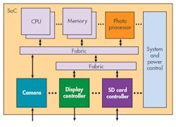
Finally, development teams are co-verifying hardware and software portions of the design together. Many large designs are currently implemented using a system-on-chip (SoC) architecture in which embedded processors play a key role (Fig. 1). The SoC’s functionality comes from a combination of hardware and software, so it’s necessary to run either production software or some sort of software-driven test cases to verify the design. An effective set of test cases should find most or all hardware bugs before running production software.
Many times, a verification team first simulates the SoC using a purely transactional UVM testbench, with the processors replaced by bus functional models (BFMs). Then, the processors are inserted to run test cases that control the rest of the SoC and coordinate with the testbench for data sent into or out of the chip. Finally, production software is run on the embedded processors for hardware-software co-verification. Since simulation speed is often a bottleneck, this phase is typically run using emulation or FPGA prototypes. Sometimes test cases are also run on these hardware platforms.
DV Trends
The first driver for the Design and Verification track is the extension of the UVM to handle analog/mixed-signal (AMS) parts of chip designs. Traditionally, analog engineers verified their designs in standalone mode using SPICE and FastSPICE circuit simulation tools. It may be possible to connect such tools to digital RTL simulators, but the resulting hybrid approach can be slow and unwieldy. These days, many analog teams first perform their SPICE runs and then model their AMS designs using real numbers so that they can run in RTL simulation.
With pseudo-analog models in the testbench, many of the good ideas of RTL verification can be extended to AMS. Features such as constrained-random stimulus and functional coverage, while initially foreign in the analog world, have an increasing role in AMS verification. An extended UVM testbench can stimulate analog inputs, check analog outputs, and measure analog coverage while doing the same for the digital portion of the design.
The second DV trend is the mainstream adoption of static and formal tools. Although commercial formal analysis has been available for many years, it found its widest application in “apps” that perform very specific verification tasks. These include analysis of clock domain crossings (CDCs), connectivity checking, verification of low-power design structures, and X-propagation checking. A well-designed app requires the user to know little about formal techniques or the automatically generated assertions that underlie the analysis performed by the app.
These apps are all static tools, requiring no simulation or simulation models. They’re sometimes called “super-lint” solutions in contrast to traditional lint tools that look for syntactic and semantic errors in RTL and testbench code. Lint tools are also static, as are equivalence checkers that check whether two versions or implementations of a design are functionally equivalent. These tools also require little knowledge of formal. The final popular category of static technology is full-fledged formal analysis.
The use of formal-analysis engines requires the ability to write assertions that specify the design’s intended behavior and constraints that guide the analysis. Although not as mainstream as formal-based apps, formal analysis is also growing in usage. Formal proof is especially important for system-level verification challenges such as power management, safety, and security. In these domains, verification engineers may seek a definitive answer to correctness, not just a lack of new bugs despite extensive simulation with high coverage metrics.
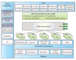
The final trend is the emerging technology of portable stimulus. Commercial tools have existed in this space for several years, and their use has grown significantly. Many observers are calling this the next step for the industry beyond UVM. The key methodology evolution is to develop a graph-based scenario model of the design and verification intent. From this model, a commercial portable stimulus tool can generate complex, self-checking test cases that can run on any verification platform.
For example, portable stimulus can generate test cases to completely cover the first (purely transactional) and second (software-driven) phases of hardware-software co-verification, as discussed earlier. In fact, it can do more than that, starting from RTL simulation of individual IP blocks or from SystemC virtual platforms and extending beyond simulation into emulation, FPGA prototypes, and silicon in the bring-up lab. The test cases generated at each stage are tuned for the strengths of each platform.
Accellera has recognized the need for an industry standard input format (Fig. 2), and the Portable Stimulus Working Group (PSWG) has been working to develop such a standard. This year’s DVCon India will include a tutorial on portable stimulus from key members of the PSWG, as well as coverage in other sessions. Furthermore, all of the vendors offering tools in this space will have booths in the DVCon India exhibition. Portable stimulus was a hot topic at both the 2014 and 2015 events, and appears likely to be so again.
Over the next few years, these six trends will affect many design and verification engineers, changing the way that their teams operate and interact with other teams in the development process. DVCon India offers a convenient opportunity to learn about these trends from academia, EDA vendors, and hands-on users. All interested parties are cordially invited to attend.
About the Author

Tom Anderson
Technical Marketing Consultant
Tom Anderson is a technical marketing consultant working with multiple EDA vendors, including AMIQ EDA. He is currently Secretary of the Accellera PSWG. His previous roles have included vice president of marketing at Breker Verification Systems, vice president of applications engineering at 0-In Design Automation, vice president of engineering at IP pioneer Virtual Chips, group director of product management at Cadence, and director of technical marketing at Synopsys.


