An off-the-shelf data acquisition (DAQ) system may cost less to purchase than a custom solution, but how well will it solve your problem? For applications requiring a special mix of measurement and stimulus types or in cases where a turnkey system is desired, employing a system integrator may provide the best solution. Working with a company that has experience directly relevant to your application can save a great deal of time and money.
As examples of optimum solutions to complex test and measurement applications, four diverse DAQ projects are presented. One was developed by a system integrator and the other three by instrument companies that also design custom test systems. Each project performs a wide range of measurements and satisfies several constraints, one system even having to survive in an extremely hostile environment.
138-kV Saturable Reactor
As part of an initiative to improve the capacity and reliability of America�s electricity grid, the Department of Energy (DOE) has established a number of high-technology projects. In one of these, SC Power Systems will develop a 138-kV saturable reactor type of fault current limiter (FCL).
SC Power Systems, a wholly owned subsidiary of Zenergy Power plc, is leading the FCL development with partners Los Alamos National Laboratory, Delta Star, Southern California Edison, and the Consolidated Edison Company of New York.
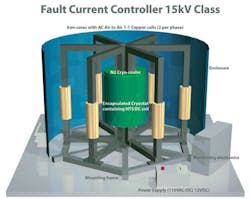
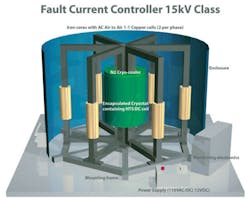
The basic principle underlying a saturable reactor is the change in inductance that corresponds to a saturated or unsaturated iron core. With a saturated core, the inductance of a winding on the core is very small. This means that large currents can flow through the winding. Conversely, when the core is not saturated, the coil has significant inductance and severely limits the flow of current.
A separate DC control winding can be used to bias the core operating point so more or less AC output current is supported. This is the way in which the three-phase fault current limiter shown in Figure 1 operates. The control winding can achieve a strong field by having many turns and a relatively low DC current. The AC power windings must carry thousands of amps, so the number of turns in those windings has to be scaled accordingly.
Figure 1. Concept Drawing of 3-Phase Saturable Core Fault Current Limiter
Courtesy of SC Power Systems
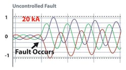
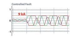
However, for the control winding, many turns of copper wire on a large structure would correspond to large winding losses. To avoid this problem, SC Power Systems is developing a high-temperature superconducting (HTS) control coil, cryogenically cooled, that will have zero resistance. Only the control current flows through the superconducting coil in this design. As Figures 2a and 2b show, a saturable reactor limits peak currents.
Courtesy of SC Power Systems
Testing
To support development of the new SC Power Systems FCL, VI Technology has designed a characterization test system and supervisory control and data acquisition (SCADA) system. They will control and monitor FCL operating parameters and capture real-time data from FCL devices being tested under a variety of operating conditions. Test data from both normal and fault conditions will be analyzed and evaluated as part of the FCL design optimization.
Don Holley, VI Technology�s marketing manager, explained, “The test system hardware includes a computer, DAQ boards, signal conditioning, measurement sensors, the cabinet enclosure, and the cabling. The sensors and transducers are mounted directly on the FCL device under test to measure AC/DC voltage and current, temperature, and magnetic flux.
“The core of the FCL is a superconducting coil enclosed in a cryo-cooler. Mass flow controllers and level sensors monitor and control the flow of liquid nitrogen required to maintain the desired core temperature.” He continued, “Load sensors mounted under the FCL measure the mechanical strain and stress caused by electrical faults imposed during testing. Cables connect the sensors and transducers to National Instruments� (NI) signal conditioning and DAQ modules. These are mounted in the DAQ system cabinet.”
The DAQ hardware is based on PXI modules, and spare slots are provided for future expansion. This high-speed system captures real-time data at 10 kS/s to ensure adequate fidelity for transient events during fault conditions.
A local PC mounted in the test facility near the FCL monitors and controls all system functions. It is linked via a fiber-optic local area network (LAN) to a remote PC with similar capabilities located in a control room.
A complementary software environment also was developed based on NI LabVIEW. Mr. Holley emphasized the importance of the graphical user interface (GUI) “which provides data visualization during the testing process and guides the operator performing the characterization testing. Raw data from the sensors is scaled and converted to the proper engineering units before being stored to hard disk. Data management utilities are provided to extract and export historical data to an Excel spreadsheet for engineering evaluation and analysis.”
Lighting a Fire Under DAQ
To advance loss prevention practices and establish new industry safety standards, a major insurance company built its own state-of-the-art research and testing complex including a destructive test facility. The cornerstone of the destructive test facility is a fire technology laboratory that conducts full-scale, real-life destructive testing research rather than relying on computer modeling.
The lab is capable of generating fires that produce greater than 20 MW of energy and collecting data on how materials and fire behave. The company can measure and learn from the rate of heat release from various configurations of materials and determine combustibility and protection requirements for commodities produced and used by the company�s clients.
Although generally satisfied with the VXI systems they had been using for almost a decade, research scientists desired greater flexibility, larger channel count, and real-time synchronization. Management also insisted that a standard testing platform be used by all researchers to permit quantifiable data comparisons. In addition, the ideal DAQ system must be able to capture large amounts of data and record it in real time because the host materials are destroyed when conducting the burn tests.
To satisfy these testing requirements, GaGe/KineticSystems offered a large-scale DAQ solution based on a FOXITM Fiber-Optic Network VXI Interface System. The company�s Marketing Manager Nicole Faubert said, “This provides a 10-MB/s interface between a host computer and VXI mainframes, permits large I/O channel counts, and allows up to a 6,560 ft distance between fiber-optic nodes. The V122 PCI Host Adapter, a fiber-optic highway, and one or more V120 VXI Slot-0 Controllers form a FOXI VXI Interface System.
“Our solution was to provide 20 VXI-based remote measurement units (RMUs), which are connected to a host PC through the FOXI interface. The RMUs consist of a V198 four-slot, C-size VXI mainframe chassis and two or three V213 64-channel scanning ADCs to handle the sensing of temperature, pressure, and on/off activity.” She added, “Although almost all hardware was standard catalog products, the challenge was to integrate and synchronize a large number of RMUs and controlling software.”
Features of the V213 ADCs include 16-b resolution, 10-Hz to 1-kHz low-pass filter options, differential inputs and programmable gain per channel, programmable limit checking and triggering with an ADC sampling rate to 50 kS/s, precision on-board reference for end-to-end calibration, and optional 4-MB multibuffer memory.
A 32-channel V200 Sigma-Delta ADC also was installed to handle the extraordinary sampling rates needed to capture data from fires ignited by explosions. The Sigma-Delta ADC features one Sigma-Delta ADC per channel, 16-b resolution at 200,000 samples/channel, programmable gain per channel, on-board DSP for limit checking, internal/external clock selection with programmable clock rate, AC/DC coupling, 8- or 32-MB multibuffer memory, simultaneous sampling and multiboard synchronization, and continuous/transient capture modes with pre- and post-trigger data collection.
The RMUs are enclosed in 12 water-cooled stainless steel cabinets for protection from heat and soot. The VXI chassis are on a raised platform to avoid explosive gases. Each RMU is equipped with a termination panel that connects to the VXI chassis through a 25-ft cable. This allows the RMUs to be placed farther from high-temperature locations.
Simultaneous acquisition on all 20 RMUs was achieved using a fiber-optic trigger bus cascaded from one RMU to the next. The 20 RMUs were integrated into the overall software application through the GaGe/KineticSystems DAQ Director Software, which allows configuration and control of all VXI Instruments. The final system provides more than 2,500 simultaneous real-time input channels.
Capturing Only the Important Parts
C&H Technologies was contacted by one of its customers experiencing long analysis time on multiple channels of digitized analog data. The analog signals were characterized by infrequent, transient activity. Because the customer simply digitized the inputs for a period of time, lengthy records resulted with comparatively little activity of interest.
A computer program was used to sort through the extensive data sets to find regions of interest and compare them to events found in a similar manner for other channels. The long analysis time was causing overall test times for the entire system to be excessive.
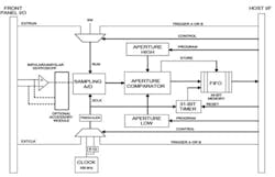
As a solution, C&H developed an Aperture ADC on an M Module for use on a VXI carrier in the customer�s VXI test system. This ADC has on-board memory for collecting up to 32 kS of 12-b data along with a 31-b time tag for each sample. The module operation is straightforward:
� Positive and negative aperture values are programmed before sampling begins. This is used to control what data actually is digitized by the ADC. When the ADC starts sampling, the first value is collected along with its 31-b time tag.
� If subsequent samples do not exceed the first by the amount of the aperture setting, no data is collected when the sample clock occurs. However, the time tag counter continues to run.
� Samples made outside the aperture window are collected, the aperture moves to new absolute values, and the data is stored along with the current time tag.
� As long as the signal is varying, the aperture window moves with the signal, and data is collected and tagged at the sampling rate. If the data again goes quiescent at a new level, storage of the samples ceases.
The result of this process is a data stream that only contains the changing data. The 31-b time tag tells where each value was in the overall collection period. With multiple channels�the customer had 48�the task of analyzing events relative to one another in time is greatly simplified and the analysis time significantly reduced.
C&H�s President Fred Harrison discussed factors the company considered when turning this specific application solution into a standard product. “We designed the module to use internal clocking, external clocking, or VXI trigger clocking (Figure 3). The Aperture ADC was designed in M Module format to allow its use in a variety of platforms such as VXI, VME, or PXI.
Figure 3. Block Diagram of Aperture A/D
Courtesy of C&H Technologies
Click here to see larger image
“The first prototype units were delivered to the customer for evaluation within their system. While the unit worked properly for the most part,” he continued, “it was decided that the addition of an anti-aliasing filter to the front end would improve the overall performance. A six-pole Butterworth filter with eight programmable corner frequencies was designed as a small mezzanine board that could be mounted on the updated Aperture ADC. In this way, customers have the option to use the ADC with or without filtering.”
Browse, Roam, Chat Forever
A high-volume manufacturer of batteries for a cell phone company originally used a test system designed with Agilent Technologies� instruments including the 3499A Switch/Control Mainframe, the 34401A DMM, 6652A and 6624A DC Power Supplies, a 6060B Electronic Load, and a 4338B Milliohm Meter.
When the cell phone battery manufacturing managers began making plans to increase production, they wanted to use newer Agilent instruments to create a test system that would reduce cost and system size while increasing throughput.
The battery manufacturer buys battery cells from different vendors, packages the cells into batteries, and tests them to make sure they meet specifications. Because several different models of cell phone batteries are tested, test speeds and rack size are critical issues. The engineering test team uses power supplies in CV mode to charge the batteries and electronic loads working in CC mode to discharge the batteries.
A thermistor monitors the working temperature of the battery, which directly relates to its output resistance. The engineering test team uses a
DMM to measure voltage, current, AC impedance, and resistance at the output. The team compares measurement results with a pass/fail criteria table.
The following tests are performed on the cell phone batteries:
� Initialization and Open Circuit Voltage: Before power is supplied, the circuit is in an undefined state. A voltage is applied to the battery terminals to put the circuit in a normal operating mode.
� Thermistor Reading: An internal thermistor is implemented in the battery as a safety measure for the cell. This test determines if the thermistor is placed properly.
� Discharge Over-Current and Recovery: If a load placed across the battery pack draws excessive current, the safety circuit opens the current pathway to prevent damage to internal components and external loads. The safety circuit closes once the load is removed. This measurement verifies proper operation of the safety circuit
� Pack AC Impedance Reading: This test determines if the battery impedance is within the desired limits.
� Charge, Over-Voltage Cutoff, and Recovery: A cell pack can become volatile if it is overcharged. When a high cell voltage is reached, the safety circuit opens the current pathway to interrupt charging. A time delay is associated with this circuit to eliminate false trips.
� Loaded Circuit Test: The circuit must be able to supply the current demanded by the host device and return to its open circuit voltage once the load is removed.
� EPROM Programming and Checksum Verification: Battery-charging information is programmed in the EPROM. The charger and phone read this data and charge the battery accordingly.
� Battery Voltage Final Verification: During end of life testing, the cell or circuit may be damaged. This test ensures no major failures occurred during testing.
Darlene Solomon, a product marketing engineer at Agilent, explained that many improvements were made in the development of the new test system. As the manufacturer had assumed, it proved to be advantageous to replace the 34401A DMM and 3499A Switch/Control Mainframe with more recently introduced products.
For example, the 34980A Switch/Measure Unit is an eight-slot mainframe that can be configured with an optional 6�-digit DMM. The list price for the 34980A with DMM is $2,315. The 34921A 40-channel multiplexer and 34938A 20-channel, 5-A switch modules add $790 and $1,078, respectively, totaling less than $4,500 for the DMM and switching functions.
This compares to the $5,500 to $6,000 cost of providing a DMM and a 3499A-based switching system with similar capabilities. The 34980A is a lower-cost solution and, because of the wide range of modules it can accept, ensures more flexible future system expansion.
Significant gains also were achieved by replacing the large and heavy 66xx linear power supplies with the modern N6700 Series supplies. For example, the N6773A module lists for $1,321 and provides a 20-V output at up to 15 A. The N6701A mainframe adds $2,643. Three more modules are used in the new system: one 20 V at 5 A Model N6743B at $885 and two lower power 20-V modules costing approximately $600 each. The N6701A-based power supply cost about $6,000.
In contrast, the 6652A and 6624A Linear Supplies list for $3,328 and $8,148, respectively. In addition to more than a $5,000 difference, the N6701A is only 1U high vs. the 3U height of the older 66xx supplies and weighs tens of pounds less.
To summarize, the new system used a 34980A Switch/Measurement Unit, 34921A Multiplexer Switches, 34938A GP Switches, an N6701A Power Supply, an N6773A Power Supply Module, an N6743B Power Supply Module, an N6733A x 2 Power Supply Module, a 6060B Electronic Load, and a 4338B Milliohm Meter.
Results Achieved
The original system with six products was 19U rack units high including the
industrial PC, and it cost about $21,735. The new system size is 37% less at 12U rack units high and, at $16,688, costs 23% less. In addition, the test time was reduced from the previous 8 s per battery.
It�s easy to see that periodic review of test-system implementation can be very beneficial. As this battery manufacturer�s business increases, were old-style test systems simply replicated, each would represent a loss of about $5,000. More than that, because the new equipment is LXI-compatible, it not only saves money, but it also provides more flexible upgrade opportunities in the future.
Summary
Test speed, hazardous environments, unusual signal characteristics, a wide variety of parameters to be measured, and system cost and size are some of the factors influencing the design of DAQ systems. Balancing these and many other constraints, such as a tight development time scale, can be a daunting prospect.
Should your company have the opportunity to develop a custom test system, discuss your plans with relevant instrument and module suppliers. New products always are being developed, and one of these might be an excellent solution to your application.
If you decide to engage the services of a system integrator, carefully examine the integrator�s previous experience. A good choice of partner will streamline your test-system development. In contrast, a poor choice will only compound the challenges you would have faced on your own.
|
FOR MORE INFORMATION |
| Agilent Technologies | 34980A Switch/Measure Unit | www.rsleads.com/709ee-176 |
| C&H Technologies | MA 200 Aperture A/D M/MA Module | www.rsleads.com/709ee-177 |
| GaGe/KineticSystems | V120 FOXI VXI Slot 0 Controller | www.rsleads.com/709ee-178 |
| VI Technology | Automated Test Services | www.rsleads.com/709ee-179 |
September 2007
