Deep-Implantable Blood-Oxygen Sensor Blends Multiple Sophisticated Technologies
You have undoubtedly seen the easy-to-use blood-oxygen saturation (SpO2) sensor that clips onto your finger and near-instantly reports results. The development of this dual-LED based unit, which sells for as low as $20, eliminated the need for costly, risky, time-consuming invasive measurements that required drawing of blood, and provides accurate results in real-time. It’s a truly amazing and illustrative example of how modern optoelectronics technologies have made “medicine” much easier, quicker, and safer, especially since this approach has no downsides versus the older blood-sample technique (see References 1 through 5).
But there’s one limitation with this fingertip-sensing technique: It can only measure oxygen saturation in the circulatory system just below the skin (the same limit generally applies to the older blood-draw approach as well, of course). Yet doctors may need to monitor that oxygen parameter deep inside the body to assess the health of transplanted organs or tissue to provide an early warning of potential transplant failure, for example.
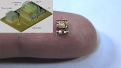
To solve this sensing problem, researchers at the University of California, Berkeley (UC-B) created a tiny, non-RF wireless implant that can provide real-time measurements of tissue oxygen-saturation levels deep underneath the skin (Fig. 1). The complete device has a volume of just 4.5 mm3 (critical for injectable implants) and is powered by ultrasound energy waves. Despite its array of component types, the entire implant is manufactured with standard medical-implant processes.
1. This general overview of the structure of the wireless, implantable blood-saturation sensor can only broadly indicate the complexity, multidisciplinary nature, and overall sophistication of this tiny device, but it provides context and a starting point.
It’s anticipated to be the first entry in a series of miniaturized sensors that could track other key biochemical markers in the body, such as pH or carbon dioxide (CO2). “It’s very difficult to measure things deep inside the body,” said Michel Maharbiz, a professor of electrical engineering and computer sciences at UC Berkeley and project leader. “The device demonstrates how, using ultrasound technology coupled with very clever integrated-circuit design, you can create sophisticated implants that go very deep into tissue to take data from organs.”
Device Design
An external ultrasonic transceiver directs energy from outside of the body toward an implant placed in muscle or deep tissue. The system merges multiple technologies for sensing, energy harvesting, and the data link. The implant has a piezoelectric crystal for energy collection and communication coupled to a luminescence sensor for O2 detection. This wireless link has two roles: It’s an acoustic link to provide power to the sensor via piezoelectric effect-driven harvesting, and it supports bidirectional data transmission.
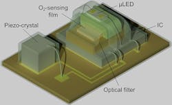
The implant (Fig. 2) consists of a piezoelectric crystal (750 × 750 × 750 μm3), a microLED, an O2-sensing film, an optical filter, a custom IC (~3.84 mm2) fabricated using a standard TSMC 65-nm low-power CMOS process, and a holder that provides mechanical support during wire bonding of the microLED. To assemble the sensor, the crystal is attached and encapsulated, and then the remaining components are assembled on the flex board.
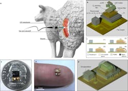
2. Wireless O2-monitoring system overview: (a) Schematic of the system as demonstrated in this paper for local tissue O2 monitoring in sheep. The free-floating wireless O2 implant is surgically placed beneath the biceps femoris muscle, and the wound is closed with sutures. The external ultrasonic transducer, placed on top of the closed surgical site, establishes a wireless acoustic link to the implant. The transducer powers the implanted sensor by delivering acoustic energy through the tissue and then listens for backscatter reflections from the sensor’s piezoelectric crystal, in which O2 data are encoded. The external transducer is driven by a custom mixed-signal system, including decoding and storage of the wireless O2 data received by the external transducer. (b) An expanded view of the wireless sensor platform, including a lead-zirconate-titanate (PZT) piezocrystal and a luminescence sensor, consisting of a µLED, a 3D-printed µLED holder, an O2-sensing film, an optical filter, and an IC. (c) The following steps were used for wireless sensor fabrication: (1) a piezocrystal was bonded with conductive silver epoxy, wire-bonded to a flexible printed circuit board (PCB) and encapsulated with parylene-C; (2) other sensor components were assembled on the flex board, and only the regions where the wire bonds are located were encapsulated with ultraviolet (UV)-curable epoxy; (3) the small gap (~50 µm) between the film and the µLED holder was filled by PDMS and (4) sensor parts excluding the piezocrystal were encapsulated with highly O2-permeable black silicone. (d,e) Schematic (d) and photograph of the wireless sensor before black silicone encapsulation and size comparison to a finger (e); scale bar, 5 mm. (f) Top view of the 4.5-mm3 packaged wireless sensor with the piezocrystal at the bottom, the luminescence sensor at the top, and a size comparison to a United States dime.
The sensor is coated with black silicone to avoid background interference by the luminescence of tissue or blood and has a detection volume of about 0.26 mm3. The crystal size and geometry is a classic engineering-design tradeoff, as it must balance the frequency-dependent acoustic loss in tissue, the power-harvesting capacity, and the impact on total implant size.
Optical Measurement
The optical arrangement that senses blood oxygen isn’t the expected LED/photodetector pairing. Instead, it’s a more complicated design that’s more suitable for being implanted in tissue. It uses what is called phase luminometry based on a biocompatible luminometric O2 “optrode,” where the phase shift between the excitation and emission optical energy is measured to determine the luminescence lifetime. The optrode consists of polydimethylsiloxane (PDMS) containing silica particles with surface-adsorbed ruthenium dyes.
When excited by photons at ~465 nm, the ruthenium dyes emit light with a peak intensity at ~621 nm. The photons emitted by the excited ruthenium dyes then undergo “collisional quenching” with O2 molecules, leading to a reduction in luminescence intensity and lifetime. Both the intensity and lifetime depend on O2 concentration.
Why do this instead of using the “simpler,” better-known LED/photosensor arrangement? Either intensity or lifetime can be measured to compute O2. Lifetime is independent of variations in light-source intensity, dye concentration, inner filter effects, and other effects, all of which are limitations of intensity-based sensors.
During operation, the emitted light is modulated by a 20-kHz square wave. An optical filter suppresses the excitation light, and a reverse-biased, on-chip photodiode detects the emission. It’s dependent on the luminescence lifetime that, in turn, is related to O2 via the Stern-Volmer equation which characterizes this phenomenon (see Reference 6).
Power and Data
Similarly, the ultrasonic power and data link is a sophisticated arrangement. When in downlink (transmit) mode, it drives the transducer with a 2-MHz carrier wave onto which it encodes digital information in discrete pulses (Fig. 3).
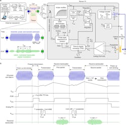
3. Block diagram of the entirely wireless O2-monitoring system: (a) The external transceiver is shown in the top left, the ultrasonic link is in the top middle, and the wireless sensor is shown at right. Top left, the external transceiver consists of TX and RX paths, where the TX path encodes downlink data onto a 2-MHz carrier. During TX operation, a level shifter boosts a low-voltage TX signal from a digital controller, and a high-voltage pulser drives an external piezo transducer. The RX path is enabled when the TX path is disabled. The reflected ultrasound backscatter from the sensor’s piezocrystal is captured by the same external piezo transducer and digitized by the RX chain. Top middle, the external piezo coupled to the outside surface of tissue produces ultrasound waves traveling through tissue; these arrive at the sensor after one time-of-flight (ToF). The downlink provides power and a transmit command for the sensor. The uplink consists of amplitude-modulated, backscattered, ultrasound waves that arrive at the external piezo two ToF periods after being sent during TX. Right, the sensor IC architecture; CLK, clock. (b) Timing diagram: The IC rectifies electrical power collected by the sensor’s piezo, and the POR initializes the O2-sensing operation. The on-off keying (OOK) demodulator detects the downlink ultrasound envelope, producing a notch. The first notch starts uplink transmission. Two data packets are transmitted via digital amplitude modulation of the ultrasound backscatter; the first packet contains five MSBs and a one-bit preamble. The uplink data are received by the external piezo when the external transceiver is switched to RX. The uplink transmission stops when the third notch duration is longer than ~64 µs (127 oscillations of a 2-MHz carrier). The IC circuitry is duty-cycled during uplink transmission to reduce energy consumption.
The implant begins harvesting energy following the arrival of an ultrasound pulse; this energy is rectified and stored on the on-chip capacitor. The uplink data transmission begins when the demodulator detects a “falling edge” in the ultrasound data input from the external transceiver. It then generates a “notch” that serves as a reference to time-synchronize the sensor IC and the external transceiver during uplink transmission, and a data packet is transmitted after a notch.
Data packets are encoded in the ultrasound reflections from the sensor’s piezo device and transmitted via backscatter amplitude modulation. This modulation is achieved by changing the electrical load resistance, which is in shunt with the piezo-device impedance. This, in turn, changes the ultrasound reflection coefficient at the piezo boundary and thus the backscatter amplitude.
Obviously, designing and then building such a complicated, multidisciplinary implant is only part of the story, as it must be tested and evaluated both in the lab and in the “field,” including implanting it into live animal tissue (in vivo) to a depth of 10 cm. Full details including photos of how this was done, along with test results, are in their lengthy but highly readable and informative paper “Monitoring deep-tissue oxygenation with a millimeter-scale ultrasonic implant” published in Nature Biotechnology. A comprehensive Supplementary Information posting has additional circuitry diagrams and actual part designations.
References
1. EE World, “Blood oxygen meters, Part 1: Background and principles”
2. EE World, “Blood oxygen meters, Part 2: IC implementations”
3. American Thoracic Society, “Pulse Oximetry”
4. American College of Physicians, “Vital signs are vital: The history of pulse oximetry”
5. US National Library of Medicine, National Institutes of Health, “Takuo Aoyagi—a Tribute to the Brain Behind Pulse Oximetry”
6. Wikipedia, “Stern-Volmer relationship”
About the Author

Bill Schweber
Contributing Editor
Bill Schweber is an electronics engineer who has written three textbooks on electronic communications systems, as well as hundreds of technical articles, opinion columns, and product features. In past roles, he worked as a technical website manager for multiple topic-specific sites for EE Times, as well as both the Executive Editor and Analog Editor at EDN.
At Analog Devices Inc., Bill was in marketing communications (public relations). As a result, he has been on both sides of the technical PR function, presenting company products, stories, and messages to the media and also as the recipient of these.
Prior to the MarCom role at Analog, Bill was associate editor of their respected technical journal and worked in their product marketing and applications engineering groups. Before those roles, he was at Instron Corp., doing hands-on analog- and power-circuit design and systems integration for materials-testing machine controls.
Bill has an MSEE (Univ. of Mass) and BSEE (Columbia Univ.), is a Registered Professional Engineer, and holds an Advanced Class amateur radio license. He has also planned, written, and presented online courses on a variety of engineering topics, including MOSFET basics, ADC selection, and driving LEDs.
Comment About the Article
To join the conversation, and become an exclusive member of Electronic Design, create an account today!

Leaders relevant to this article: