Lighting products based on light-emitting diodes (LEDs) are gaining a stronger foothold in many different application areas—consumer, commercial, industrial, and even military products. LEDs provide illumination in everything from automotive headlights to outdoor systems. Key to the design of these LED-based products is proper thermal management: LEDs that run too hot can suffer reduced operating efficiency and dramatically shortened operating lifetimes. Therefore, thermal design becomes critical to maintaining LED p-n junction temperatures that fall within the recommended limits for those devices.
This file type includes high resolution graphics and schematics when applicable.
This report will review some of the LED types currently being used and the impact of elevated diode junction temperatures on them. It will also explore different LED thermal-management approaches and materials that have proven effective in reducing LED junction temperatures, as well as briefly look at some of the computer simulation software that can help mitigate the design challenges involved in flowing heat away from the LEDs.
LED lighting is often considered an efficient means of electrical illumination compared to older illumination technology, such as incandescent lighting. But LED lights, like incandescent bulbs, generate their fair share of heat. In a typical LED, 70% to 80% of the electrical power applied to the LED converts to waste heat energy that must be removed from the LED. For an LED mounted on a printed-circuit board (PCB), heat typically flows from the LED p-n junction to its solder joints and mounting points, and then to the PCB material and a heat-dissipating component (e.g., a heat sink) for dissipation to the ambient environment.

LEDs come in many forms and package styles, such as standard LED lights (Fig. 1), ceiling lights, parabolic aluminized reflector (PAR) lights, bay lights, and street lights. Their power levels vary widely, resulting in many different levels of generated heat and much different requirements for thermal management.
For example, standard LED lights typically replace traditional incandescent bulbs for indoor lighting applications. Though operating at much lower power levels (less than 10 W) than incandescent bulbs, they still require thermal management. LEDs used in other applications, such as outdoor lighting and ceiling lights, have higher power levels (and thus generate more heat), which demands more comprehensive thermal-management solutions like larger heat sinks.
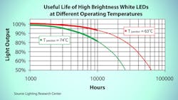
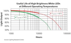
Heat can wreak havoc on an LED, since excess heat will impact performance and operating life expectancy. Every 10°C rise above the maximum operating-temperature limit can reduce an LED’s lifetime by as much as 50% (Fig. 2).
Higher operating temperatures also result in reduced lighting efficiency for an LED, with less light output at higher LED PN junction temperatures. Furthermore, the operating temperature can affect the color of light produced by an LED. For spectrum-sensitive applications, the optical wavelength of an LED can shift with increasing operating temperature, with elevated operating temperatures contributing to poor system performance or even system failures.
Simply put, effective thermal management becomes more important as the industry moves to higher-power/brightness LEDs and higher-density LED arrays, which are generating more power and heat in smaller spaces. Practical thermal management makes it possible to maintain a suitable LED junction operating temperature even with the increasing power density of LEDs and LED arrays.
Transferring Heat
Heat transfers away from a source such as an LED by means of conduction, convection, and radiation. For PCB-mounted LEDs, heat flows from the LED via conduction to a structure with higher thermal conductivity, such as a heat sink, where it can be dissipated through convection to the environment. The challenge here is to surround the LED with thermally conductive materials and structures that will shift the heat away, but also fit the mechanical requirements of the PCB or product design.
Materials for LED thermal management can be compared in terms of their thermal conductivity, which measures the amount of heat that can be conducted through a material. Comparisons can also be made in terms of thermal resistance, which measures the temperature rise through the material for a given amount of applied power, such as 1.2°C/W, referenced to specific convection flow conditions.
A PCB, such as FR-4, combines electrically/thermally conductive materials (copper conductors) and more electrically/thermally resistive materials (dielectric material). The high thermal resistance of the dielectric material results in hotspots if thermal management isn’t applied to heat-generating devices such as LEDs.
In some cases, PCBs are fabricated with metal backsides and plated through holes (PTHs) from the circuit side to provide a thermal path. For applications with high-power (high-temperature) LEDs, PCBs will often feature a metal-core (MC) base. Such PCBs typically use a thermally conductive metal, such as aluminum or copper, as the supporting substrate. The PCB also incorporates a thermally conductive thin dielectric layer that helps a mounted LED transfer heat through the PCB and allows the board to function as a heat spreader. While this represents effective thermal management at the PCB level, it’s also more expensive than a standard PCB.
Often, the heat flow from LEDs through a PCB must be assisted by additional materials and structures, such as thermally conductive adhesive materials and other thermal interface materials (TIMs), heat sinks, and heat pipes. LEDs are usually encapsulated in a transparent resin material, which is a poor thermal conductor, so a thermally conductive path must be provided by means of those additional materials and components. When heat transfers to another structure, such as a heat sink, it can then be dissipated by means of convection and radiation. In some LED designs, the placement of a heat sink may be limited by the design’s mechanical requirements, requiring a thermally conductive path to a remote heat sink via heat pipes or other thermally conductive structures and materials.
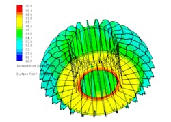
At the design stage, numerous computer-aided-engineering (CAE) programs provide effective tools for simulating the thermal impact of different materials and structures, such as heat sinks, on an LED’s performance and operating lifetime (Fig. 3). Many of these programs use computational-fluid-dynamics (CFD) analysis to develop heat-flow solutions and thermal structures that can significantly reduce the junction temperatures even in higher-power LED lights.
When coupled with measured data, such software can provide solutions to minimize the operating temperatures of even higher-power LEDs. For example, Mentor Graphics’ FloTHERM CAE software and associated modules have been beneficial in predicting the thermal behavior of different LED lighting products. And the company’s FloEFD thermal-modeling software can predict the thermal effects of LEDs used as automotive headlights.
By comparing simulations with measured data from working LEDs, using thermal-characterization test equipment like Mentor’s T3Ster, LED models and simulations can be refined to more closely reflect actual operating conditions and thermal effects. Additional-thermal modeling/simulation tools include the Sauna thermal-modeling software developed by Thermal Solutions (www.thermalsoftware.com), and tools from SolidWorks and Flomerics.
Thermal Management
LED power levels vary widely, from a few watts for indoor lights to hundreds of watts for high-power outdoor LEDs. As a result, heat levels generated for these devices vary widely, requiring different thermal solutions to manage LED operating temperatures. When mounting an LED in an application circuit, thermal adhesives and TIMs are often used to improve the thermal conductivity from the LED to the surrounding circuitry. Because they’re conformable, these materials can fill the air gaps around LEDs to help avoid hotspots and interruptions in the thermal flow away from the LED.
With PCBs, as noted earlier, different materials exhibit different thermal characteristics and thermal conductivities. Copper, which typically forms the electrical signal paths on PCBs, has high thermal conductivity (401 W/m-K at +25°C), although it’s expensive when fabricating heat-dissipating structures such as heat sinks. Therefore, LED heat sinks will typically incorporate aluminum, which has a thermal conductivity of 205 W/m-K at +25°C. In addition, using a thermal coating can enhance a heat sink’s thermal radiation and thermal performance.
Mechanical design of LED heat sinks runs the gamut, and they feature an array of thermal capabilities. Some are small enough to be incorporated into an LED package, while larger heat sinks are often mounted remotely from an LED, with a thermal path required between the two components. LED heat-sink solutions can be assessed in terms of their heights and physical size, their thermal resistance, and their power-dissipation capabilities. In general, heat sinks must provide a larger surface area to dissipate larger amounts of heat. Thus, more power/heat-handling capabilities mean an increase in size.
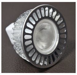
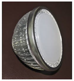
One example of a lower-power LED thermal solution using a heat sink is the LEDBLM01XX (Fig. 4). The aluminum structure, which includes a lens along with the heat sink, dissipates heat/power levels to 5 W. The component weighs 16 g and comes with a number of different thermal-coating materials to enhance the heat flow away from the LED.
For considerably higher power/heat levels, there’s the LEDHBE02XX—a much larger heat-sink assembly that weighs 1.4 kg (Fig. 5). It provides thermal dissipation up to 180 W. It incorporates an aluminum fin and heat sink and, like the lower-power heat-sink assembly, can be supplied with different thermal coating materials to enhance thermal performance.
LED heat-sink solutions like these are designed and fabricated using different technologies. CTS Corp., for example, leverages two types of technology: cold-forged and non-solder stamped heat sinks. Cold-forged heat sinks generally provide larger surface areas than extruded heat sinks, while non-solder stamped heat sinks offer high-aspect-ratio heat fins along with large surface areas. Once again, adding specialized thermal coatings can the performance of both heat-sink types.
In some cases, active solutions are needed when passive thermal management isn’t sufficient for removing the heat from an LED or LED array. These may include cooling by means of a liquid-flow mechanism to and from the LED or by forced-air cooling (fans). Many LED heat-sink suppliers also offer versions of heat sinks with built-in fans to minimize the amount of space occupied by the LED thermal-management solution. Of course, any active solution requires power, which increases an LED circuit’s power consumption.
In conclusion, to ensure operating efficiency and maximize operating lifetime, proper thermal management of LEDs is essential. Modern software tools and LED thermal-management components, such as heat sinks help make that possible.
This file type includes high resolution graphics and schematics when applicable.
About the Author
Terry Luxmore
Kent Roff and Leon Lu
Comment About the Article
To join the conversation, and become an exclusive member of Electronic Design, create an account today!

Leaders relevant to this article: