As the provider of an AR platform built for quick creation of AR instructions, training materials, and service and support documentation, a question we often get is: “How do we make our own AR instructions if we don’t have 3D models?”
It’s a valid question. Organizations generally leverage a product’s CAD assets (3D engineering models) to create augmented-reality training and instruction materials. Many enterprises are working in exactly that way and have no difficulty achieving that workflow. If you’re in that category, then congratulations, you can probably grab a coffee.
However, there are several scenarios where this approach doesn’t work:
- “We need to assist our employees on equipment that’s supplied by a vendor.”
- “The CAD files exist and we own them, but we’re struggling to get them released to us.”
- “This equipment pre-dates our CAD software.”
The good news is that most of these scenarios are likely to be short-lived. Where IP protection is a concern, for instance, CAD files can be converted and simplified at source to maximize the value to instruction while minimizing the exposure of proprietary information. In addition, the very nature of self-authoring keeps that exposure limited to your internal content authors and pre-approved workforce across a secure network. As the benefits of AR instruction and assistance become more commonly understood, these barriers are starting to fall.
In the meantime, though, it can be extremely useful to have techniques for these situations, and we thought we would share a few as well, as publish a demonstration project specifically made with no supplied or “made-to-order” 3D content as an example. We chose a basic car maintenance example that’s commonplace and straightforward, but also a good reference point for more complex situations.
Less is More
One key thing to understand is that good AR instructions are really about adding as little to the user’s workspace as possible. While movies tend to portray augmented reality as the ability to add as much content as possible, the fact is that this doesn’t work well. A user can only pay attention to so much information at once. So, for best results, an optimal goal is to provide small, but key, additions to the space, which will have maximum impact.
From this perspective, having complex 3D models of the equipment isn’t actually beneficial. For example, when working on an engine, the engine is already there; we have no need to reproduce it. For a large variety of processes, arrows, circular beacons, basic tools, and simple shapes are all that’s required to communicate everything your user needs to know—particularly when they’re animated effectively and placed exactly where the user needs them. The right authoring software will include these things, along with the ability to place video and images. For common objects that aren’t included, it’s also a good idea to look for support for standard file formats that make adding third-party content (from public websites, etc.) a simple process.
Context is King
Under these circumstances, the AR author is still left with one significant challenge. You start your project, secure in the knowledge that a combination of simple content is more than enough to communicate exactly what your end-user needs to know… as long as they’re placed accurately in the workspace. Without a model of your equipment in the scene, however, how can you place your content? You need a reference framework of some kind: context.
There are numerous strategies for establishing this framework. One method is to take some measurements and create some simple 3D shapes to represent key landmarks in your work area. This can be effective for straightforward situations, and if you have ready access to your equipment, some trial and error may be an acceptable approach.
If the area you want to present instructions in is basically flat or even a series of flat spaces, such as a control panel, another option could be to take photos (carefully, and square to the camera) and bring those images into your project as stand-ins. However, for more complex, demanding projects, it may be worth the effort to create 3D objects that are more representative of the actual equipment. 3D models can be built at various levels of detail, and there’s ample middle ground between detailed CAD models and simple shapes.
Although this skill set isn’t available in every organization, it’s also not particularly challenging or expensive to access. For some projects, it may be worth the relatively small expense of generating some models for this purpose. This method is particularly important if your process demands an extended disassembly or assembly process, where layers of parts are needed.
Reality Capture
For circumstances where the area is more complex or where access is more challenging, what’s needed is some form of reality capture. This term covers a broad variety of options, but the essence is basically the same… the ability to go into a space and quickly generate a 3D model of it without any particular skills.
These models can be extremely useful for providing context, but you will not have the ability to “disassemble” them. Such models will represent a contiguous surface with no recognition of where one object ends and another begins. This is great for providing a reference framework so that you can use it as a map for placing your instruction. You will likely not show this type of model to your end user, though.
Here are some of the major options:
Laser scanning: If you have access to laser-scanning equipment or your budget allows for contracting these services, this can be an effective way to get a surface model of a work area.
Photogrammetry: This is a relatively simple approach, requiring only access to a camera and some inexpensive software. Essentially, the process is to take a large number of photographs (>100) of a work area from a wide variety of angles and distances and use the software to generate a textured 3D model. While results can vary, and depending on the software you may have to manually scale the resulting model, this technique can be quite useful in the right circumstances.
Depth camera/3D sensor: This option is our current preferred method. It involves utilizing a handheld depth camera—either built into a smartphone or as an external accessory to a tablet or smartphone—where you can walk around an area and generate a simple textured 3D model “on the fly.” Formats used are compatible with good authoring software. As a result, you can bring the model in immediately and use it as quite an accurate reference for placing content.
Results from all of these methods can provide workable results, but detail levels vary. Since the goal here is to enable a rapid reference framework to be put in place; low detail levels are entirely acceptable for the less expensive approaches.
Test Drive
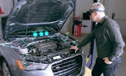
If you’re interested in this approach, we’ve created a sample project that illustrates how to do it, called “A3 Maintenance Demo,” that you can view within our free WorkLink app (click here). It’s designed to take full advantage of the Microsoft HoloLens, but you can also view it on a handheld device. To view the project in AR, log in to the WorkLink app as a guest and load the A3 project, then either use a standard Scope AR marker or “Interactive Mode” (on handheld devices) to view it. Check out this video on the project:
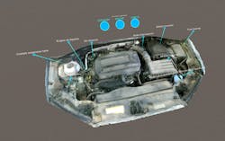
A few additional notes about the project: The project includes a series of maintenance instructions designed to be viewed directly on the vehicle itself. We’ve included some additional content strictly to help demonstrate the concepts discussed here. The car outline is a commercial 3D model, but is included only to provide context for those viewing the instructions away from the car, and would not otherwise be needed.
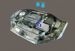
The engine model itself was scanned in about 15 minutes using a smartphone with a 3D-depth camera. In this case, an Asus Zenfone AR. Again, when viewing these instructions on the vehicle itself, this model would not normally be included. We’ve included it in the demo to show what type of results can be expected from this sort of process, and to help viewers understand the context of these instructions. Visibility switches (blue spheres) are provided to allow you to show and hide the various models. Turn off the car body and engine to view the instructions as they would appear when seen on the real car.
Graham Melley is Co-founder and Principal of Scope AR.
About the Author
Graham Melley
Co-founder and Principal
Graham Melley, co-founder and principal of Scope AR, provides active leadership in the development and support of the most advanced and effective enterprise AR tools in the market. Graham has led the content design and creation of groundbreaking solutions for some of the largest organizations in the world, including the likes of Boeing, Toyota and Lockheed Martin.
Graham’s extensive experience in AR content creation and background in 3D animation and communication helped shape the backbone of Scope AR’s WorkLink AR authoring platform, opening the door for creating these highly effective tools to a new generation of authors already fluent in their own industrial expertise.


