Enhanced PWM Implementation Adds High-Performance DAC to MCU
This file type includes high resolution graphics and schematics when applicable.
Sometimes a design needs more DACs than the mixed-signal microcontroller has available. An easy solution is to put in a pulse-width modulator (PWM) circuit and filter it output with an RC filter. An 8-bit digital/analog converter (DAC) can have 20-mV resolution from a PWM operating from a 5.0-V supply, and it's reasonable to require the AC noise on the RC filter's output to be less than a single bit.
The PWM output as seen in the frequency domain is:
where d is the duty cycle, f is the pulse rate (typically the PWM clock frequency divided by the Period value), and n is the harmonic number. At 50% duty cycle, the peak-to-peak value of the first harmonic is 2 × 5 × (2/π) or 6.18 VPP from a 5.0-V supply. To get this "noise" below a single bit requires a filter with attenuation of 20 mV/6.18 V = –50 dB at the first harmonic. That means the RC filter must attenuate the sum of the PWM's harmonics by a factor of 300.
At duty cycles above and below 50%, the peak-to-peak noise at the fundamental is lower, so the filtering gets easier. If the PWM is clocked at 8.0 MHz with 50% duty cycle, the output pulse rate is 31.25 kHz. Attenuating the noise to 20 mVPP takes a filter with a corner frequency of 104 Hz. That results in a slow update rate when you change the 'DAC' (PWM) value. That's not a problem if the DAC is meant to be static, as for a reference voltage.
However, if you want a faster update rate, it's a problem. Using more filter poles don't help, they attenuate mostly the upper frequencies and slow the response without reducing the low-order harmonics. A better way to reduce the noise in the DAC is to modulate the PWM output randomly using a Stochastic Signal Density Modulator (SSDM). This is a melding of a PWM and a linear feedback shift register (LFSR) (Fig. 1).
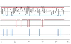
The LFSR outputs a series of 2n-1 numbers in a pseudorandom order. At each step, the LFSR output is compared to a threshold value in an n-wide digital comparator. When the LFSR output is smaller than the threshold value, the SSDM output is a logical '1'; when the output is larger than the threshold value, the SSDM output is a logical '0' (Fig. 2), where there SSDM output is shown for two different threshold values.
The average density of the SSDM’s output is the same as the duty cycle of the PWM, but the SSDM output is scattered about on the PWM period in a pseudorandom manner. The density of the SSDM is modified by an 8-bit number in code, essentially identical to changing the duty cycle of a PWM.
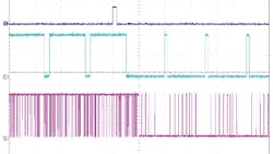
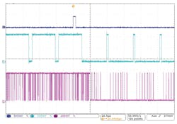
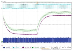
A project was built in a PSoC microcontroller with PWM and SSDM at the same duty cycle and density. In the first half of the display (Fig. 3), the duty cycle of the PWM and the density of the SSDM are at 94%. In the second half, the duty cycle of the PWM and the density of the SSDM are at 6%.
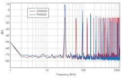
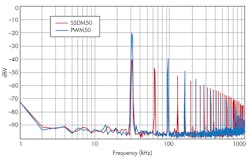
A look at the results for PWM and SSDM outputs at the same frequency and duty cycle/density, as seen on a spectrum analyzer, shows that the low-frequency content of the SSDM is lower than the PWM (Fig. 4). Therefore, it should be easier to filter.
With density and duty cycle at 50%, the first harmonic of the SSDM waveform is –13 dBV (450 mVPP), which is 20 dB lower than that of the PWM. The harmonic content of the SSDM waveform is lower than the PWM up through the 8th harmonic (Fig. 5). The SSDM has higher-level components in the upper frequency range, but these are easily filtered to the level at which they don’t affect the total noise level. The filter corner frequency is a tradeoff between lower for noise reduction and higher for faster settling. It takes a filter on the SSDM output with a corner frequency of 1.4 kHz to keep the peak-to-peak pulse noise level below the one-bit resolution. The same filter on a PWM output results in 10 counts (200 mV) of periodic noise.
At the 8th harmonic, the SSDM output is 2.0 mVPP, which is one-tenth that of the target noise level. Toggling the PWM and SSDM from one duty cycle and density shows that the rise time and settling time are the same for PWM and SSDM, as they have the same RC filter. The filtered SSDM output clearly has lower periodic noise (Fig. 6).
PWMs can be easily incorporated into almost any microcontroller. The SSDM can be implemented in standard logic in Cypress PSoC microcontrollers, CY8C3xxx, 4xxx, or 5xxx, using PSoC Creator. The density is modified at run time by writing to a control register; the comparator is simply an 8-wide implementation. The PWM, used here for comparison, is a standard component with the duty cycle also modified at run time.
The SSDM implementation is somewhat simpler in PSoC1 (CY8C24xxx, 27xxx, 28xxx, and 29xxx) with the 8-bit SSDM being a built-in function of the digital block. The length of the SSDM sequence (used here for comparison) is set in the GUI, and the density is selected by using a dedicated API in C, with this code: SDM_WriteDensity (hex value).
The RC filter is, of course, off-chip. The result of the SSDM implementation is a PWM-based DAC with the same peak-to-peak voltage noise as a standard PWM DAC, but with ten times the bandwidth. Wider DACs and SSDMs of 10, 12, or 16 bits can be implemented by using more digital blocks in PSoC1 or by using flip-flops and XORs up to 16 bits in PSoC4xxx. The higher-resolution DAC will have correspondingly slower update rates.
Acknowledgement
Dave Van Ess (the most stochastic of my friends) did the original work creating the SSDM User Module in Cypress PSoC Designer and drove the demand for including this functionality in all new PSoC designs.
About the Author
Dennis Seguine
Technical Staff
Dennis Seguine is a member of the technical staff at Cypress Semiconductor Corp. He has been an applications engineer for Cypress Semiconductor since 2000, following many years of analog, embedded system, and software design for the underwater, instrumentation, and medical industries.
