Power Management Chapter 12: Wireless Power Transfer

This articles is part of the Power Management Series in the Power Management section of our Series Library.
Download this article as a .PDF eBook.
You can employ wireless power transfer at different power levels. At the low power level, wireless power transfer is intended for smartphones and other portable battery-powered systems. Higher-power wireless transfer is used to recharge the battery in an electric vehicle. First, we will describe the lower power technology in an FAQ format. Next, we will describe work done at the Oak Ridge National Laboratory for wireless charging batteries in an electric vehicle.
Is there a wireless power transfer standard for portable phones?
Wireless power transfer is based on the Wireless Power Consortium’s WPC 1.1 Standard (July 2012) that facilitates cross-compatibility of compliant transmitters and receivers. The Standard defines the physical parameters and the communication protocol used in wireless power transfer.
The Wireless Power Consortium’s global standard for compatible wireless charging is called Qi (pronounced “chee”). The Qi standard guarantees that any device carrying the Qi logo will work with any charging surface that carries the Qi logo, regardless of manufacturer or brand. Qi allows design freedom, product differentiation, and guaranteed wireless charging interoperability.
How does wireless power technology work?
Wireless power transfer relies on magnetic induction between planar receiver and transmitter coils. Positioning the receiver coil over the transmitter coil causes magnetic coupling when the transmitter coil is driven. Flux couples into the secondary coil, which induces a voltage and current flows. The secondary voltage is rectified and transferred to the load, wirelessly. Wireless power transfer is usually controlled by two ICs: one transmits and another receives the transferred power, as shown in Fig. 12-1.
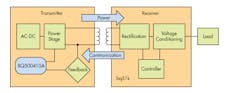
12-1. Qi-compliant wireless power transfer receivers and transmitter circuits. The bq500410a is a Texas Instruments transmitter IC. Companion receiver ICs include the bq51050B, bq51051B, bq51011, bq5013, bq51013A, and bq51013B.
How do the receiver and transmitter ICs provide the wireless transfer?
The power-transfer receiver IC provides efficient ac/dc power conversion as required to comply with WPC 1.1 communication protocol. Control algorithms provide an effective and safe Li-Ion and Li-Pol battery charger—eliminating the need for a separate battery charger circuit.
By utilizing near-field inductive power transfer, a secondary coil embedded in the portable device can pick up the power transmitted by the primary coil. The ac signal from the secondary coil is then rectified and conditioned to apply power directly to the battery. Global feedback is established from the secondary to the primary in order to stabilize the power transfer process. This feedback utilizes the WPC 1.1 power communication protocol.
What determines the power transfer?
Power transfer depends on coil coupling, which depends on the distance between coils, alignment, coil dimensions, coil materials, number of turns, magnetic shielding, impedance matching, frequency, and duty cycle. Receiver and transmitter coils must be aligned for best coupling and efficient power transfer. The closer the space between the two coils, the better the coupling. However, to account for housing and interface surfaces, the practical distance is set to be less than 5 mm, as defined within the WPC Standard. Shielding is added as a backing to both the transmitter and receiver coils to direct the magnetic field to the coupled zone. Magnetic fields outside the coupled zone do not transfer power. Thus, shielding also serves to contain the wireless fields and avoid coupling to other adjacent system components.
Does the WPC 1.1 Standard set the operating environment for power transfer?
You can control power transfer by varying any one of the coil coupling parameters. However, for WPC compatibility, the transmitter-side coils and capacitance are specified and the resonant frequency point is fixed. Power transfer is regulated by changing the frequency along the resonance curve from 112 kHz to 205 kHz (that is the higher the frequency is, the lower the power). Duty cycle remains constant at 50% throughout the power band and is reduced only once 205 kHz is reached.
What coil configurations are available?
Fig. 12-2 shows the A6 three-coil configuration with a 70 x 20 mm charge surface area as well as the A1 single-coil with 18 mm ×18mm charge space. The 70 mm by 20 mm A6 charge area is 400% larger than 19-mm by 19-mm area used by an A1 coil.
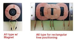
12-2. The transmitter IC can employ either of two type of coil configurations. On the left is the A1 single coil and on the right is the A6 three-coil configuration.
An A6 coil arrangement can achieve greater than 70-percent efficiency. The WPC Standard establishes coil and matching capacitor specification for the A6 transmitter. Although the transmitter is intended to drive an A6 three-coil array, it can also be used to drive a single A1 coil. For single-coil operation, the two outer coils and associated electronics are simply omitted.
The performance of an A6 transmitter can vary based on the design of the A6 coil set. For best performance with small receiver coils under heavy loading, it is best to design the coil set so that it is on the low end of the specified tolerance.
Does the WPC standard set the coil characteristics?
The WPC standard describes the dimensions, materials of the coils, and information regarding the tuning of the coils to resonance. The value of the inductor and resonant capacitor are critical for proper operation and system efficiency.
Why is capacitor selection important?
Capacitor selection is critical to proper system operation. The resonant tank requires a total capacitance value of 68 nF +5.6 nF center coil, which is the WPC system compatibility requirement. Capacitors chosen must be rated for at least 100 V and must be of a high-quality C0G dielectric (sometimes also called NP0). They typically have a 5% tolerance, which is adequate. The designer can combine capacitors to achieve the desired capacitance value. Various combinations can work depending on availability.
Can you monitor power transfer efficiency?
Both parasitic metal detection (PMOD) and foreign object detection (FOD) can continuously monitor the efficiency of the established power transfer. This protects against power lost due to metal objects in the wireless power transfer path. Combining input power, known losses, and the value of power reported by the RX device being charged, the transmitter can estimate how much power is unaccounted for and presumed lost due to misplaced metal objects. Exceeding this unexpected loss indicates a fault and halts power transfer.
PMOD has certain inherent weaknesses as rectified power is not ensured to be accurate per the original WPC1.0 Specification. However, the FOD algorithm uses information from an in-system characterized and WPC1.1 certified receiver and it is therefore more accurate. Where the WPC1.0 specification requires merely the rectified power packet, the WPC1.1 specification additionally uses the received power packet that more accurately tracks power used by the receiver. As default, PMOD and FOD share the same threshold-setting resistor for which the recommended starting point is 400 mW.
How do the receiver and transmitter ICs communicate?
Communication within the WPC standard is from the receiver to the transmitter, where the receiver tells the transmitter to send power and how much. To provide regulation, the receiver must communicate with the transmitter whether to increase or decrease frequency. The receiver monitors the rectifier output and, using Amplitude Modulation (AM), sends packets of information to the transmitter. A packet is comprised of a preamble, header, actual message, and a checksum, as defined in the WPC standard.
The receiver sends a packet by modulating an impedance network. This AM signal reflects back as a change in the voltage amplitude on the transmitter coil. The signal is demodulated and decoded by the transmitter-side electronics and the frequency of its coil-drive output is adjusted to close the regulation loop.
Oak Ridge National Laboratory’s Demos 20kW, EV Wireless Power Transfer System
A 20 kW wireless charging system for electric vehicles was demonstrated recently at the Department of Energy’s Oak Ridge National Laboratory (ORNL). The charging system achieved 90% efficiency at three times the rate of plug-in systems commonly used for electric vehicles.
ORNL’s power electronics team achieved the world’s first 20 kW wireless charging system for passenger cars by developing a unique architecture that includes an ORNL-built inverter, isolation transformer, vehicle-side electronics, and coupling technologies. For the demonstration, researchers integrated the single-converter system into an electric Toyota RAV4 equipped with an additional 10kW-hour battery (Fig. 12-3).

12-3. WPT system installed in an electric Toyota RAV4 equipped with an additional 10kW-hour battery.
The researchers are already looking ahead to their next target of a 50kW wireless charger, which would match the power levels of commercially available plug-in quick chargers. Providing the same charging speed with the convenience of wireless charging could increase consumer acceptance of electric vehicles and is considered a key enabler for hands-free autonomous vehicles. As the researchers advance their systems to achieve higher power levels, one of their chief concerns is maintaining safety for the equipment and associated personnel.
Original work on wireless started about three years ago and was described in a paper presented by nine ORNL researchers in a 2013 IEEE Transportation Electrification Initiative (TEI) e-Newsletter. According to David Smith, vehicle systems program manager “wireless power transfer (WPT) represents a paradigm shift in electric-vehicle (EV) charging that offers the consumer an autonomous, safe, and convenient option to conductive charging and its attendant need for cables. Today’s technology is a stepping stone toward electrified roadways where vehicles could charge on the go.”
The 2013 newsletter said WPT can be fully autonomous due to the vehicle and grid side radio communication systems, and is non-contacting; therefore, issues with leakage currents, ground faults, and touch potentials do not exist. It also eliminates the need for dealing with heavy, bulky, dirty cables and plugs. It eliminates the fear of forgetting to plug-in and running out of charge the following day and eliminates the tripping hazards in public parking lots and in highly populated areas such as malls, recreational areas, etc. Furthermore, the high-frequency magnetic fields employed in power transfer across a large air gap are focused and shielded, so that fringe fields (i.e., magnetic leakage fields) attenuate rapidly over a transition region to levels well below limits set by international standards for the public zone (which starts at the perimeter of the vehicle and includes the passenger cabin).
The ORNL approach to WPT charging places strong emphasis on radio communications in the power regulation feedback channel augmented with software control algorithms. The goal for this WPT is minimization of vehicle on-board complexity by keeping the secondary side content confined to coil tuning, rectification, filtering, and interfacing to the regenerative energy-storage system (RESS). WPT charging represents the end game in the context of the connected vehicle, wireless communications, and eventually, with in-motion deployment of WPT, the ultimate in electric vehicle operation with unlimited range: dynamic wireless charging. Oak Ridge National Laboratory is working toward more efficient coil designs, power electronics converter developments, and communications systems, as well as new control strategies in this field. ORNL WPT programs also define and address concerns related to personal safety and hazards that may arise. ORNL uses electromagnetic resonance inductive coupling system for wireless charging of electric vehicles.
ORNL is the lead organization for this activity and partners with Toyota Motor Corp., Evatran, Clemson University ICAR Center, Cisco, Duke Energy, and International Rectifier. With OEM, commercialization, communications, grid, and device partners, ORNL meets the aggressive power and efficiency goals for future’s electric vehicles with stationary and in-motion charging capabilities. At the end of the first phase, ORNL demonstrated 6.6kW and 10kW power transfer over 160mm gap with over ~>90% dc-to-dc efficiency, ~97% coil-to-coil efficiency, and 85% end-to-end (wall outlet to vehicle battery terminals) efficiency. The demonstration used dedicated short range communication (DSRC) systems for vehicle side data monitoring and feedbacks for controlling the grid side units.
Fig. 12-4 is the block diagram of the original ORNL wireless power transfer system. The grid side unit of the WPT system consists of an active front-end rectifier (AFER) with power factor correction (PFC), a high-frequency power inverter, a high-frequency isolation transformer, a tuning capacitor, and the primary coil. On the secondary (vehicle) side, the secondary coil is in parallel with the tuning capacitor, a diode-bridge rectifier, and a filter capacitor.
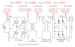
12-4. Block diagram of the ORNL WPT system with five cascaded power conversion stages.
Active Front-end Rectifier
Fig. 12-5 shows the active front-end rectifier with power factor correction. In the AFER converter, only left leg of the active front-end rectifier is utilized and the right leg acts as a diode phase-leg. The AFER can work as a boost power factor correction circuit and is capable of boosting grid voltage’s peak value up to 10 times (normally 2-3 times).
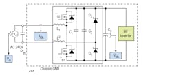
12-5. Active front-end rectifier with power factor correction.
The AFER with PFC can also be interleaved for higher power rating. For high efficiency, low loss, and high switching frequency and reduced current ripple, it uses APT100MC120JCU2 SiC MOSFET phase-leg modules. The converter is operated based on the reference power to be delivered to the vehicle battery. Basically, depending on the battery reference current, a PI (proportional integral) controller is used to determine the reference current magnitude from the grid. A phase-locked-loop (PLL) system determines the grid voltage phase angle and the grid reference current is shaped accordingly. An outer PI controller uses the actual grid current and the internally generated reference ac current and determines the switching states. With the selected architecture, ORNL achieved a power factor of >98% and current total harmonic distortions (THDI) of <5%. In addition, because the AFER regulates the primary side DC link voltage, the battery current ripple is reduced to <10 A.
Coupling Coil Design
Electromagnetic design of WPT coupling coils provides the most fundamental investigation into their performance. At ORNL, the WPT team developed couplers based on the magnetic vector potential at a field point due to current flowing in an ideal primary coil conductor. The potential at this field point is defined to lie at the location of the secondary coil. For a coil pair of radius a, assuming infinitesimal conductor radius, and having a coil to coil spacing z, then the radius vector from the primary coil origin to the field point becomes

(Fig. 12-6). The corresponding vector potential, Aφ, for the case of N1 primary turns and I1 A yield a primary excitation of N1I1 amp-turns.
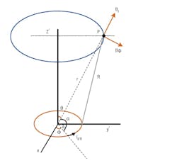
12-6. Vector field analysis diagram (analytical construction) for coupling coil design.
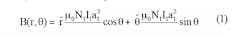
At the field point P, the magnetic vector potential is strongly dependent on primary coil radius, total current, the co-elevation angle θ, and inverse with the square of the separation distance, r. However, it is the flux density B(r, θ), and total flux Φ at the secondary coil that is most relevant to WPT performance and is given as:
High Frequency Inverter
Load conditions; i.e., state-of-charge of the battery and coupling coefficient; i.e., vehicle coil to primary pad gap and any misalignment between transmit and receive coils determine the frequency response of the WPT system. The amount of power transferred to the secondary coil is governed by the switching frequency, duty cycle, and the input voltage of the inverter. This relationship can be expressed as:
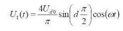
Where:
Ud0 = HF power inverter rail voltage
d = pulse duty ratio
ω = angular frequency
Although the primary coil voltage can be controlled by the active front-end converter to vary the dc rail voltage Ud0, the ultimate objective is to dynamically change the switching frequency and the duty cycle in order to achieve the best operating conditions in terms of efficiency and power transfer. In the ORNL laboratory setting, the HF power inverter voltage was adjusted using a power supply. In a commercialized version of this WPT technology, a dedicated short-range communication (DSRC) link as shown in Fig. 12-4 would be needed. The transmitter side of the DSRC collects the measurement data such as battery voltage, battery current, and battery management system (BMS) messages needed for regulation. The grid-side receiver side of the DSRC channel receives this information for control purposes along with supporting primary side measurements. Then, a DSP-based embedded control system determines the switching frequency and the appropriate duty cycle according to the control law being used. The switching signals for the inverter IGBTs are generated by the DSP control algorithm and applied to the HF power inverter gate drives. The control system can also regulate the inverter power based on the reference power commands that can be received through the V2I communications from a smart grid compliant utility.
Portions of this article were prepared by the Oak Ridge National Laboratory, operated by the UT-Battelle for the U.S. Department of Energy under contract DE-AC05-00OR22725. Accordingly, the U.S. Government retains a non-exclusive, royalty-free, license to publish from the contribution, or allow others to do so, for U.S. Government purposes. The research team included Omer C. Onar, Steven Campbell, Cliff White, Larry Seiber, Chester Coomer, Lixin Tang, Paul Chambon, Madhu Chinthavali, and John M. Miller.
Read more articles from the Power Management Series in the Power Management section of our Series Library.
About the Author

Sam Davis
Sam Davis was the editor-in-chief of Power Electronics Technology magazine and website that is now part of Electronic Design. He has 18 years experience in electronic engineering design and management, six years in public relations and 25 years as a trade press editor. He holds a BSEE from Case-Western Reserve University, and did graduate work at the same school and UCLA. Sam was the editor for PCIM, the predecessor to Power Electronics Technology, from 1984 to 2004. His engineering experience includes circuit and system design for Litton Systems, Bunker-Ramo, Rocketdyne, and Clevite Corporation.. Design tasks included analog circuits, display systems, power supplies, underwater ordnance systems, and test systems. He also served as a program manager for a Litton Systems Navy program.
Sam is the author of Computer Data Displays, a book published by Prentice-Hall in the U.S. and Japan in 1969. He is also a recipient of the Jesse Neal Award for trade press editorial excellence, and has one patent for naval ship construction that simplifies electronic system integration.
You can also check out his Power Electronics blog.
Comment About the Article
To join the conversation, and become an exclusive member of Electronic Design, create an account today!

Leaders relevant to this article: