Power Management Chapter 18: Electronic Lighting

This articles is part of the Power Management Series in the Power Management section of our Series Library.
Download this article as a .PDF eBook.
Electronic lighting using LEDs is one of today’s most rapidly evolving technologies. The major reason for this growth is the development of white LEDs whose efficiency keeps increasing. By 2020, the U.S. Department of Energy (DoE) estimates that commercial LED lighting efficiency will be as high as 258 lumens per watt, or two and a half times as efficient as today’s fluorescent lamps, resulting in 90% energy savings. By then, the DoE predicts the cost of LEDs will fall by 80% and global penetration will be 60%.
With an average lifespan of over 100,000 hours, LEDs last more than 10 times longer than any other light source. However, LED lifetimes are rated differently than incandescent lights that fail when the filament breaks. One definition for an LED’s typical lifetime is the average number of hours until light falls to 70% of initial brightness.
The commercial LED marketplace calls for low-cost lighting, which requires minimal cost components. LEDs operate with a dc voltage so the incoming ac must be rectified and reduced to a low voltage for the LED driver. The LED power circuit can be non-isolated so it may not need an input transformer. However, there is one component that must be chosen carefully, the electrolytic or tantalum capacitor used in the rectifier circuit. Although the LED may have a long lifespan, the capacitor’s lifetime will probably be shorter. Electrolytic capacitor have a tendency of drying out and failing. Therefore, the manufacturer must minimize the capacitor’s cost while selecting a capacitor with a long lifespan.
Heating is an important design issue for LEDs and other lighting devices. An incandescent bulb gives off 90% of its energy as heat, and a compact fluorescent bulb wastes 80% as heat. LEDs don’t heat as much as other light sources, but it is an issue that has required various heat-control techniques whose cost doesn’t have a major impact on overall cost.
White LEDs
AlGaInP is one of the two types of LED materials now used for lighting systems. The other is indium gallium nitride (InGaN). Slight changes in the composition of these alloys changes the color of the emitted light. AlGaInP produces red, orange, and yellow LEDs. InGaN produces green, blue, and white LEDs.
Emergence of AlGaInP and InGaN materials for LEDs made commercial LED lighting feasible. These two materials allowed white light to be produced by mixing LEDs from different parts of the lighting spectrum.
Now, there are two approaches to creating white light. One is to mix the light from several colored LEDs to create a spectral power distribution that appears white. By locating red, green, and blue LEDs adjacent to one another, and properly mixing the amount of their output, the resulting light appears white.
Another approach to generating white light is to use phosphors for a short-wavelength LED. When illuminated by a blue LED light, one phosphor emits yellow light with a broad spectral power distribution. The remaining blue light, when mixed with the yellow light, results in white light. Additional phosphors are being developed to produce soft white and bright white lighting.
Improved LED Bulb
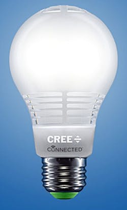
Cree Inc. has introduced what it considers a better LED bulb, delivering an even better light with better performance, a longer life, and more energy savings (Fig. 18-1). The new Cree LED bulb is built to deliver true LED performance in color quality, light output, and dimming. It has an improved longer lifetime of over 27 years (30,000 hours), lasting as much as six times longer than some LED bulbs. Its proven 4Flow Filament Design, which ensures that it looks and lights like a traditional incandescent. The new bulb also provides consumers with a higher color rendering index of 83 to better display colors, true ENERGY STAR-compliant omnidirectional distribution for all-around light, and is fully dimmable with most standard dimmers and suitable for enclosed fixtures.
18-2. The LT3744 is burst-mode 3A LED driver with 98% efficiency.
The LT3744’s peak current mode controller maintains ±3% LED current regulation over a wide voltage range from VEE to VIN. By allowing VEE to float to negative voltages, several LEDs can be driven from a single Li-Ion battery with a simple, single step-down output stage. Additionally, this enables a unique inverting step-down topology that allows a single common anode heat sink to be used for RGB LEDs. A frequency-adjust pin allows the user to program the frequency between 100 kHz and 1 MHz, optimizing efficiency while minimizing external component size. Combined with its 5mm × 6mm QFN package, the LT3744 offers a very compact 80-watt LED driver solution.
The LT3744 provides both PWM dimming and CTRL dimming, which offer 3,000:1 dimming capability for four LED current levels, ideal for color mixing applications, such as those required in DLP projectors. Similarly, its unique topology enables it to transition between two regulated LED currents in less than 2µsec, enabling more accurate color mixing in RGB applications. LED current accuracy of ±3% is maintained to offer the most accurate brightness of light emitted from the LED. Additional features include output voltage regulation and open-LED and shorted-LED protection, open-drain output fault flag, frequency synchronization, and thermal shutdown.
With so many dimmers being used with incandescent lamps, several companies have shown conversion circuits that replace the incandescent with an LED. A typical triac lamp dimmer circuit for an incandescent lamp consists of the circuit in Fig. 18-3. The triac can conduct in either direction so it cuts both halves of the ac sine wave input, as shown in Fig. 18-4. Varying potentiometer (R1) varies the amount of the ac waveform that is cut, which varies the incandescent lamp brightness.
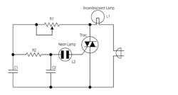
18-3. Triac dimmer circuit for an incandescent lamp.
An incandescent lamp is resistive so the voltage and current through the lamp have a linear relationship. Due to the thermal inertia of the incandescent lamp’s filament, the pulsed input voltage of Fig. 18-4 does not cause the light output to flicker. In contrast, the LED is a nonlinear load in which lamp current and voltage depend on the diode-like performance of an LED. Furthermore, the LED responds much faster than an incandescent lamp to changes in applied voltage. Thus, the 120 Hz triac drive voltage can appear as flicker using an LED, unless a “smart” LED driver modifies the triac output to eliminate flicker.
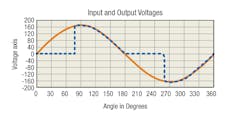
18-4. For the triac-based incandescent trimmer, the blue line indicates the switching of the triac.
Among the new “smart” LED drivers intended for use with existing triac dimmers are iWatt’s iW3616 and iW3617 from iWatt (Fig. 18-5), now part of Dialog Semiconductor. They are two-stage ac/dc power-supply controllers optimized for dimmable LED luminaires. The iW3616 is rated at 12W and the iW3617 has a 25W rating. Both controllers are compliant with the IEC61000-3-2 standard for electromagnetic compatibility (EMC). Its proprietary Flickerless technology automatically detects the dimmer type and phase, providing compatibility with analog and digital dimmers.
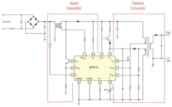
18-5. iW3616 control circuit converts a dimmer from an incandescent to an LED lamp.
Most LEDs can be dimmed using pulse width modulation (PWM). Incandescent lamps have thermal inertia that allows a relatively low PWM frequency to avoid visual flicker during dimming. In contrast, LEDs light up very quickly and require a higher frequency PWM to avoid flicker. There has been some concern that dimming light causes a loss of energy. However, the opposite is true. Driver efficiency may be reduced slightly during dimming, but it can also save significant energy. Plus, dimming lights to half power will save overall significant energy and actually extend LED lifespan.
The MAX16834 from Maxim Integrated is a current-mode, high-brightness LED (HB LED) driver designed to control a single-string LED current regulator with two external n-channel MOSFETs (Fig. 18-6). The MAX16834 integrates all the building blocks necessary to implement a fixed-frequency HB LED driver with wide-range dimming control. The MAX16834 allows implementation of different converter topologies such as SEPIC, boost, boost-buck, or high-side buck current regulator.
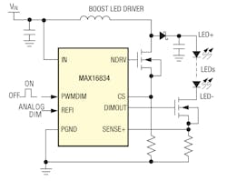
18-6. Maxim’s MAX16834 current-mode, high-brightness LED (HB LED) driver.
The MAX16834 features a constant-frequency, peak-current-mode control with programmable slope compensation to control the duty cycle of the PWM controller. A dimming driver offers a wide-range dimming control for the external n-channel MOSFET in series with the LED string. In addition to PWM dimming, the MAX16834 allows for analog dimming of LED current.
The MAX16834 switching frequency (100kHz to 1MHz) is adjustable using a single resistor from RT/SYNC. The MAX16834 disables the internal oscillator and synchronizes if an external clock is applied to RT/SYNC. The switching MOSFET driver sinks and sources up to 3A, making it suitable for high-power MOSFETs driving in HB LED applications, and the dimming control allows for wide PWM dimming at frequencies up to 20kHz.The MAX16834 is suitable for boost and boost-buck LED drivers.
The MAX16834 alone operates over a 4.75V to 28V input supply range. With a voltage clamp that limits the IN pin voltage to less than 28V, it can operate in boost configuration for input voltages greater than 28V. Additional features include external enable/disable input, an on-chip oscillator, fault indicator output (FLT) for LED open/short or overtemperature conditions, and an overvoltage protection circuit for true differential overvoltage protection.
Texas Instruments’ LP5521 is a three-channel LED driver designed to produce variety of lighting effects for mobile devices (Fig. 18-7). A high-efficiency charge pump enables LED driving over full Li-Ion battery voltage range. The device has a program memory for creating variety of lighting sequences. When program memory has been loaded, the LP5521 can operate autonomously without processor control allowing power savings.
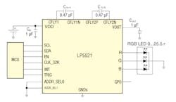
18-7. Texas Instruments’ LP5521 is a three-channel LED driver designed to produce a variety of lighting effects.
The device maintains excellent efficiency over a wide operating range by automatically selecting proper charge pump gain based on LED forward voltage requirements. The LP5521 is able to automatically enter power-save mode, when LED outputs are not active and thus lowering current consumption.
Three independent LED channels have accurate programmable current sources and PWM control. Each channel has program memory for creating desired lighting sequences with PWM control.
The LP5521 has a flexible digital interface. A trigger I/O and 32-kHz clock input allow synchronization between multiple devices. Interrupt output can be used to notify the processor when LED sequence has ended. LP5521 has four pin-selectable I2C-compatible addresses. This allows connecting up to four parallel devices in one I2Ccompatible bus. GPO and INT pins can be used as digital control pins for other devices. The LP5521 requires only four small and low-cost ceramic capacitors.
Comprehensive application tools are available, including command compiler for easy LED sequence programming.
Texas instrument’s LP5521 is a three-channel LED driver designed to produce variety of lighting effects for mobile devices. A high-efficiency charge pump enables LED driving over full Li-Ion battery voltage range. The device has a program memory for creating variety of lighting sequences. When program memory has been loaded, the LP5521 can operate autonomously without processor control allowing power savings.
The IC maintains excellent efficiency over a wide operating range by automatically selecting proper charge pump gain based on LED forward voltage requirements. The LP5521 is able to automatically enter power-save mode, when LED outputs are not active and thus lowering current consumption.
Three independent LED channels have accurate programmable current sources and PWM control. Each channel has program memory for creating desired lighting sequences with PWM control. The LP5521 has a flexible digital interface. A trigger I/O and 32-kHz clock input allow synchronization between multiple devices. Interrupt output can be used to notify processor, when LED sequence has ended. LP5521 has four pin-selectable I2C-compatible addresses. This allows connecting up to four parallel devices in one I2Ccompatible bus. GPO and INT pins can be used as a digital control pin for other devices.
The LP5521 requires only four small and low-cost ceramic capacitors. Comprehensive application tools are available, including command compiler for easy LED sequence programming.
Eight-Switch Matrix IC Controls On/Off/Dimming and Diagnostics of LED Array
The LT3965 from Linear Technology is an LED bypass switching IC that contains a floating matrix of eight 17V/330mΩ NMOS switches (Fig. 18-8). You can connect the eight switches in parallel and/or in series to bypass current around any one of LEDs in a string. When interfaced with an external constant current driver IC, the combination can control dimming and diagnostics for up to eight individual LEDs or LED segments. An I2C serial interface in the switch matrix provides the ability to control individual LEDs. Fig. 18-8 shows the LT3965 with an external constant current LED driver (LT3955). You can independently program each of the eight channels to control each LED in the string in four different ways:

18-8. LT3965 with an external constant current LED driver (LT3955).
• Constant LED on
• Constant LED off
• LED Dimming without fade transition
• LED Dimming with fade transition
The LT3965 operates over the VDD input supply range of 2.7V to 5.5V and VIN range of 8V to 60V. A –40°C to 85°C junction temperature version, LT3965EFE, is housed in a 28-lead TSSOP thermally enhanced package that ensures a compact footprint for matrix dimming applications. An industrial temperature version, the LT3965IFE, guarantees operation from a –40°C to 125°C operating junction temperature range.
Typical applications include automotive matrix LED headlights, industrial lighting and large LED display lighting. TheI2C serial interface enables digital programming with 256:1 dimming ratios with or without the 11-bit resolution fade transition between the dimming states. Each switch can control and monitor a single LED or a segment of up to 16V of series-connected LEDs. The LT3965’s 8V to 60V input voltage range can accommodate a wide range of LED drivers commonly used in automotive and industrial applications.
LED Power Supplies
The emerging field of electronic lighting has produced families of power supplies specifically for LEDs. For example, Mean Well has introduced the NPF-40D series, a single-output, waterproof switching power supply (Fig. 18-9). Along with its LED driving function, the supply has built-in 3-in-1 dimming (0 to10VDC, PWM signal, or resistance), which simplifies brightness adjustment that allows light reduction and energy conservation. The entire series offers universal input range from 90VAC to 305 VAC and incorporates a PFC function. The enclosure is in a 94V-0 flame-retardant case. The interior is fully potted with silicone that enhances heat dissipation and allows the supply to meet the anti-vibration demand up to 5G. It also conforms to IP67 level, enabling the NPF-40D to be used in a very dusty and humid, harsh environment.

18-9. Mean Well’s NPF-40D series, a single-output, waterproof switching power supply.
The supply has up to 90% efficiency and no load power consumption below 0.5W. It has protection for short circuit, overcurrent, overvoltage, and overtemperature. It can satisfy the energy-saving demand for the new generation of LED lighting. A double-insulation weather-resistant input cable allows users to install various types of lighting systems. The entire series can operate from -40°C to 70°C and comply with the relevant global lighting safety certification.
LED Testing
Because of their production processes, LEDs cannot be manufactured with 100% consistent optical properties. Brightness and color can vary substantially from component to component even in the same production batch. This is why LEDs have to be tested during production and in their final application. Comprehensive optical characterization is also essential during research and development of LEDs and for LED-based products. Tests are required to determine luminous intensity, luminous flux, color, spectrum, and spatial radiation pattern of LEDs.
The Instrument Systems’ LED Tester (Fig. 18-10) is a turnkey test system based on the company’s CAS 140CT CCD Array Spectrometer, Keithley Series 2400/2600 Sourcemeter, and a control PC combined with tester software developed in-house. The interplay between all the components has been optimized for the tough conditions of continuous application in production environments.

18-10. LED Test System
This LED Tester can measure critical measuring parameters, e.g., color coordinates of white LEDs, extremely precisely and reproducibly. All calibrations are based on the PTB and NIST national reference standards. The Keithley 2600 delivers fast current supply to the LEDs and in this way permits short measurement times.
The tester software comprises a user-friendly interface with a multitude of functions. You can select different results and structure their display on the monitor to suit the application. The hardware setup is provided with an entering page in order to configure parameters and settings for each application.
Read more articles from the Power Management Series in the Power Management section of our Series Library.

About the Author

Sam Davis
Sam Davis was the editor-in-chief of Power Electronics Technology magazine and website that is now part of Electronic Design. He has 18 years experience in electronic engineering design and management, six years in public relations and 25 years as a trade press editor. He holds a BSEE from Case-Western Reserve University, and did graduate work at the same school and UCLA. Sam was the editor for PCIM, the predecessor to Power Electronics Technology, from 1984 to 2004. His engineering experience includes circuit and system design for Litton Systems, Bunker-Ramo, Rocketdyne, and Clevite Corporation.. Design tasks included analog circuits, display systems, power supplies, underwater ordnance systems, and test systems. He also served as a program manager for a Litton Systems Navy program.
Sam is the author of Computer Data Displays, a book published by Prentice-Hall in the U.S. and Japan in 1969. He is also a recipient of the Jesse Neal Award for trade press editorial excellence, and has one patent for naval ship construction that simplifies electronic system integration.
You can also check out his Power Electronics blog.
Comment About the Article
To join the conversation, and become an exclusive member of Electronic Design, create an account today!

Leaders relevant to this article: