
This articles is part of the Power Management Series in the Power Management section of our Series Library.
Download this article as a .PDF eBook.
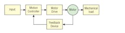
The key component in a motion system is the motor because it determines the design of the associated motion controller as well as the motor drive. From a power-management viewpoint, the important motion-system design considerations are providing the appropriate control signals as well as the required drive power for the specific motor. Each motion controller is unique for a specific motor. Fig. 19-1 shows the typical motion system that includes a motion controller and a motor drive.
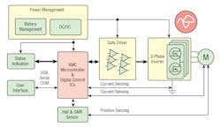
19-4. Control system for an SRM senses angular position, which is sent to the controller. Deriving the position in the time domain allows computing the angular speed of the rotor. The controller compares the actual speed with the reference value and calculates the error signal for the hysteresis comparator. Each phase is supplied within a certain rotor position range in order to maximize the developed torque. The hysteresis controllers send the gate signals to the power switches of the converter.
The SRM has no brushes or permanent magnets, and the rotor has no electric currents (Fig. 19-4). Instead, torque comes from a slight misalignment of poles on the rotor with poles on the stator. The rotor aligns itself with the magnetic field of the stator, while the stator field stator windings are sequentially energized to rotate the stator field.
The magnetic flux created by the field windings follows the path of least magnetic reluctance, meaning the flux will flow through poles of the rotor that are closest to the energized poles of the stator, thereby magnetizing those poles of the rotor and creating torque. As the rotor turns, different windings will be energized, keeping the rotor turning. The SRM motion controller must provide the appropriate signals.
Induction Motor
An induction motor is an asynchronous ac motor where power is transferred to the rotor by electromagnetic induction, much like transformer action. An induction motor resembles a rotating transformer, because the stator (stationary part) is essentially the primary side of the transformer and the rotor (rotating part) is the secondary side. Polyphase induction motors are widely used in industry. Fig. 19-4 shows a microcontroller-based induction motor drive.
Currents induced into this winding provide the rotor magnetic field. The shape of the rotor bars determines the speed-torque characteristics. At low speeds, the current induced in the squirrel cage is nearly at line frequency and tends to be in the outer parts of the rotor cage. As the motor accelerates, the slip frequency becomes lower, and more current is in the interior of the winding. By shaping the bars to change the resistance of the winding portions in the interior and outer parts of the cage, effectively a variable resistance is inserted in the rotor circuit. However, the majority of such motors have uniform bars.
Servo Motor
A servomotor is a motor, very often sold as a complete module, used within a position-control or speed-control feedback control system mainly to control valves, such as motor-operated control valves (Fig. 19-5). Servomotors are used in applications such as machine tools, pen plotters, and other process systems. Motors intended for use in a servomechanism must have well-documented characteristics for speed, torque, and power. The speed vs. torque curve is quite important and is high ratio for a servo motor. Dynamic response characteristics such as winding inductance and rotor inertia are also important; these factors limit the overall performance of the servomechanism loop. Large, powerful, but slow-responding servo loops may use conventional ac or dc motors and drive systems with position or speed feedback on the motor. As dynamic response requirements increase, more specialized motor designs such as coreless motors are used. AC motors’ superior power density and acceleration characteristics compared to that of dc motors tends to favor PM synchronous, BLDC, induction, and SRM drive applications.
19-7. Texas Instruments’ DRV8811 is a motor microstepping motor driver with two H-bridge drivers, as well as microstepping indexer logic to control a stepper motor.
Read more articles from the Power Management Series in the Power Management section of our Series Library.

About the Author

Sam Davis
Sam Davis was the editor-in-chief of Power Electronics Technology magazine and website that is now part of Electronic Design. He has 18 years experience in electronic engineering design and management, six years in public relations and 25 years as a trade press editor. He holds a BSEE from Case-Western Reserve University, and did graduate work at the same school and UCLA. Sam was the editor for PCIM, the predecessor to Power Electronics Technology, from 1984 to 2004. His engineering experience includes circuit and system design for Litton Systems, Bunker-Ramo, Rocketdyne, and Clevite Corporation.. Design tasks included analog circuits, display systems, power supplies, underwater ordnance systems, and test systems. He also served as a program manager for a Litton Systems Navy program.
Sam is the author of Computer Data Displays, a book published by Prentice-Hall in the U.S. and Japan in 1969. He is also a recipient of the Jesse Neal Award for trade press editorial excellence, and has one patent for naval ship construction that simplifies electronic system integration.
You can also check out his Power Electronics blog.
Comment About the Article
To join the conversation, and become an exclusive member of Electronic Design, create an account today!

Leaders relevant to this article: