Power Management Chapter 23: Transportation Systems

This articles is part of the Power Management Series in the Power Management section of our Series Library.
Download this article as a .PDF eBook.
Power management plays a vital role in transportation systems that travel on land, air, and sea. Regardless of the particular application or technology, power management regulates, controls, and distributes power throughout that system.
Land transportation includes the automotive industry, whose requirements are specific and different from most industrial and commercial applications. Some of these power-management requirements are similar to the general requirements for power supplies, whereas some are exclusive to the automotive industry: reverse polarity protection, load dump, alternator overvoltage, peak current, water resistance, and vibration. The main issues for electronic equipment in the automotive industry are:
• Cost
• Reliability
• Electromagnetic compatibility (EMC).
The requirements for the automotive industry are much closer to military requirements, but the cost must be significantly lower. List 23-1 lists the main requirement and conditions of electronic equipment for the automotive industry.
Semiconductors
At the heart of an automotive power converter are the power semiconductors. Clearly, the main types of power semiconductors used in the automotive industry are MOSFETs, IGBTs, and bipolar transistors. For automotive applications, it is preferable to use semiconductors with a gate threshold voltage of 2-4V or higher. With a lower gate threshold, semiconductor reliability will be reduced or the cost of the gate drive will increase significantly. Consider semiconductors with logic level threshold or GaN type devices, although GaN has the additional penalty of higher cost. For low voltage, below 200V, obviously a MOSFET is straightforward to use. For high voltage, there is a choice: MOSFETs, IGBTs, bipolar transistors, or a combination thereof.
During the last 15 years the EMI requirements for electronic units for automotive applications has become more stringent, from CISPR25 class 2 to class 4. The main reason is the demand for compatibility. A contemporary vehicle has many electronics units on board and the tendency is for these numbers to grow. Each unit needs to operate without interfering with other units on the vehicle. The next point about EMI is the slew rate of voltage. This slew rate shouldn’t be higher than 2500V/µS, and it’s better when it is 1500V/µS or less. In this case, EMI will be reduced, reliability will be increased, and the cost of the EMI filter itself and shielding will be reduced.
Troubleshooting is included in the cost of the product. If the product is more reliable, it results in a cost reduction of the product for the customer. In the automotive industry, this requirement is much stronger because of the price of troubleshooting is much higher than in the industrial and commercial markets. That’s why more reliable design is preferable.
List 23-1. Requirements and Conditions for Automotive Electronic Equipment
1. Sources: battery and alternator
2. Load dump overvoltage from alternator
3. Reverse polarity protection
4. Jump-start stresses
5. High efficiency under light load and low consumption at idle and key off
6. Peak currents up to 2900A at 12V
7. Overvoltage spikes to 800V
8. Electromagnetic compatibility
9. CAN-bus communication capability
10. Life time, reliability
11. Mechanical challenges: Water resistance and vibration
12. Operational temperature -40°C to +110°C
13. Development cycle-time pressures
Roadster Strives for 400-Mile Range
EV pioneer Tesla Motors will employ several improvements that could achieve a 40% to 50% improvement on range between the original Roadster and the new Roadster 3.0 (Fig. 23-1). There is a set of speeds and driving conditions where the company is confident it can drive the Roadster 3.0 over 400 miles on a single charge.
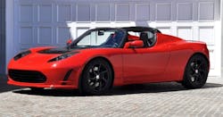
23-1. Tesla predicts that its Roadster 3.0 will have a 400-mile driving range.
The company notes that battery technology has had continued steady improvement in recent years, as it has also had in optimizing total vehicle efficiency through Model S development. The company has wanted to apply the experience gained from its first vehicle, and are going to do that with the prototype Roadster 3.0 package. It consists of three main improvement areas.
The original Roadster battery was the very first lithium ion battery put into production in any vehicle. It was state of the art in 2008, but cell technology has improved substantially since then. It has identified a new cell that has 31% more energy than the original Roadster cell. Using this new cell, it has created a battery pack that delivers roughly 70kWh in the same package as the original battery.
Aerodynamics
The original Roadster had a drag coefficient (Cd) of 0.36. Using modern computational methods it expects to make a 15% improvement, dropping the total Cd down to 0.31 with a retrofit aero kit.
The original Roadster tires have a rolling resistance coefficient (Crr) of 11.0 kg/ton. New tires for the Roadster 3.0 have a Crr of roughly 8.9 kg/ton, about a 20% improvement. It is also making improvements in the wheel bearings and residual brake drag that further reduce overall rolling resistance of the car.
Appointments for upgrading Roadsters will be taken this spring once the new battery pack finishes safety validation. Tesla is confident that this will not be the last update the Roadster will receive in the many years to come.
In addition, CEO Elon Musk said, “We are actually working on a charger that automatically moves out from the wall and connects like a solid metal snake. This can be used with all existing Model S cars, not just future ones.”
Last year, Tesla produced more than 22,000 cars; this year it is on track to build about 35,000. By the end of 2015, it will have increased production by another 50%. With Model X on the horizon, Dual Motor Model S now in production, and increasing global demand, the company decided to temporarily pause production in order to increase capacity at the Tesla Factory in Fremont, Calif.
During the pause in production, the company:
• Upgraded the assembly line
• Added capacity to the body shop
• Enhanced powertrain assembly
• Revamped facilities for its employees.
The result of this retooling phase, which complemented ongoing upgrade work, is a much-expanded operation that allows the company to produce more cars, faster, while increasing automation and providing a more inviting work environment.
Musk said that the most dramatic changes are to be found in general assembly, where Tesla eliminated a lot of overhead steel and mechanical structures in favor of advanced robots that can lift and maneuver entire cars with optimum precision while taking up less room. Soon, these new robots will even be able to install battery packs in the cars, relieving humans of the most labor-intensive operation in the factory and reducing installation time from four to two minutes.
Alongside the robots, Tesla created a more efficient floor plan with significantly more automation. In addition, the cars now move down the assembly line as associates work on them, enabling a streamlined and more consistent workflow. The line is now running at about 1,000 cars a week with the potential for significantly more with minor adjustments.
In the powertrain department, Tesla added conveyors and advanced robots that have given them the capacity to process 1 million battery cells per day, up from 800,000. In body-in-white, they’ve added new welding equipment and improved production uptime by 5% to 10%, thanks in part to a 13-car buffer that guards against bottlenecks. Also added are 24 new tire and export docks to the perimeter of the main building, increasing the speed with which it can deliver cars overseas.
As well as making the plant brighter by installing skylights, replacing fluorescent lights with energy-saving LED lamps, and painting previously gray walls and floors a bright white, they’ve added a few novel touches. For instance, they wrapped several pillars with climbing plants to add some greenery to the surroundings. They had a comic artist depict the manufacturing process in a series of illustrations, which were printed on the glass walls enclosing some of the robots. And they’ve added a wall of framed photos showing the factory building in different guises over its 54-year existence.
Sit Back and Enjoy the Ride …. to Work
At the 2016 Consumer Electronics Show (CES), Volvo revealed that it is developing intelligent, high-bandwidth streaming capabilities with its technology partner, Ericsson, that will ensure drivers and passengers get the most out of their time traveling in an autonomous Volvo (Fig. 23-2). Power management is an important design consideration for autonomous cars because of the different voltages necessary for sensors and mechanical controls.

23-2. An autonomous Volvo lets the “driver” relax.
Volvo recently unveiled its design vision for fully autonomous cars with Concept 26. Now it is actively working on future solutions to deliver the best user experience in fully autonomous mode. Imagine a highway full of autonomous cars with their occupants sitting back watching their favorite TV shows in high definition. “This new way of commuting will demand new technology, and a much broader bandwidth to ensure a smooth and enjoyable experience,” said Anders Tylman, general manager, Volvo Monitoring & Concept Center at Volvo Car Group.
Volvo Cars’ ongoing research into autonomous driving has confirmed what we all know—that the daily commute is taking the joy out of driving. It is during the commute and on long-haul motorway trips that people are most willing to delegate the act of driving to their car.
With this in mind, Volvo has developed Concept 26, named to reflect the average daily commute to work of 26 minutes—time that could be spent doing something more meaningful than sitting in stop-and-go traffic. Volvo has set out to bring choice and freedom back to the driver; to enjoy the driving experience when they want to, or to delegate driving to the car when they want to do something else.
By learning the most common routes and times of travel and understanding media preferences, future Volvo cars will be able to provide one-click navigation and a customized preference based list of potential media—allowing customers to choose routes and select content tailored to the amount of autonomous time that is available during their commute.
“With our future autonomous drive technology, we will provide people with the freedom to choose the way they would like to commute and the content they would like to experience,” said Tylman.
Drive, Create, Relax
“It’s all about people,” said Robin Page, vice president of Interior Design at Volvo Cars.
“Our research clearly shows that some people will want to use their commuting time creatively when they have full autonomous drive available, while others will want to just sit back and relax, watch online media, or listen to music. Autonomous drive will make all of this possible. This is what Concept 26 has captured by reimagining the entire car experience.”
Concept 26 is based around an all-new patented seat design that actively cradles the driver during the transformation phase into one of the three modes: Drive, Create or Relax. With these three modes, the concept creates a new autonomous drive innovation platform that can adapt to new needs and technologies over time.
When the driver wishes to delegate driving to the car the steering wheel retracts, the seat reclines, and a large display emerges from the dashboard, allowing the driver to enjoy the time spent in the car as they like. Concept 26 embraces the need for radical change of the basic design of car interiors and provides a space that can be used as the driver/passenger wishes.
Concept 26 opens up a new paradigm of possibilities in the car—from entertainment to service provision and beyond, using the technology that is now a natural part of our everyday lives. It also signals the huge potential for new business opportunities and high-tech collaborations that autonomous drive will bring.
“We have gone to great lengths to understand the challenges and opportunities that autonomous cars will bring to people in coming years, and our flexible approach to engineering and design, enabled by our new Scalable Product Architecture, means that we can readily bring this from concept to reality,” said Dr. Peter Mertens, senior vice president, research and development at Volvo Car Group.
Volvo Cars’ ongoing Drive Me research project, which will see an extended fleet of fully autonomous cars driving real customers on the roads of Gothenburg, Sweden, in 2017 is further proof that Volvo is a leader in autonomous drive technology, building firmly on its foundation of safety.
“Volvo Cars is among the first to address the subject of self-driving cars and liability. We firmly believe that car makers should take full responsibility for the actions of the car when it is driving in full autonomous mode. If a manufacturer does not accept liability, it clearly implies that they are not confident about their autonomous drive technology,” said Mertens.
Taking Flight Powered by the Sun
Air transportation today includes Solar Impulse, the solar-powered airplane that flew across the U.S. and landed in New York’s Kennedy airport. It includes high-tech and innovative power electronics subsystems, including solar panels, batteries, and motors.
Solar Impulse is a one-of-a-kind aircraft whose technology highlights the exclusive use of sun power for a transcontinental flight (Fig. 23-3). “Our airplane is not designed to carry passengers, but to carry a message,” said pilot Bertrand Piccard. Pilot Andre Borschberg noted that “from the very start of the project we understood that our primary goal was to save energy.”
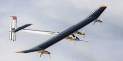
23-3. The wing of the HB-SIA is filled with solar cells used to charge the batteries that power the motors and cockpit electronic systems.
The first Solar Impulse from San Francisco, and made stops in Phoenix, Dallas, St. Louis, Cincinnati, and Washington, D.C., before landing in New York City in May 2013. The 3,511-mile journey took 105 hours and 41 minutes in the air. Average speed was 33.14 mph. Piccard and Borschberg alternated piloting the airplane.
The U.S. flight employed version HB-SIA of the Solar Impulse; actually a prototype of what is envisioned as the forerunner of an airplane that will circumnavigate the world, the HB-SIB (Solar 2), whose construction began in 2011. The HB-SIB will have a larger cockpit that will allow the pilot to fully recline during flights lasting four to five days. It will have an increased payload, its electrical circuits will be isolated to enable flights in rain, and system redundancy will improve reliability. Its advanced avionics will allow trans-oceanic travel. Wingspan of the HB-SIB is 262.5 ft. compared to 208 ft. for the HB-SIA.
Solar Impulse HB-SIB required development of new materials and new construction methods. For example, Solvay has invented electrolytes that increase the batteries energy density. Bayer Material Sciences is allowing the project to make use of its nanotechnologies. The fuselage is using carbon fibers that weigh less than any previously seen. The carbon fiber sheets are only 25g/m2, which is three times lighter than paper. By using carbon fiber construction, the aircraft will weigh about the same as an average automobile.
The aircraft will undergo the same structural strength and vibration testing as the HB-SIA. Flight testing was done in 2014, and a round-the-world flight began in 2015.
Solar Panels
There were about 12,000 solar cells on the HB-SIA’s wings and horizontal stabilizer. The HB-SIB will have 15,000 of them. This is more impressive than it appears because the panel-building process is all handmade. Plus, the cells are 150 microns thick and rated at 45kW, peak power. Cells were selected for their lightness, flexibility, and efficiency, which is 22%. SunPower Corp. provides the cells, which are then meticulously put together one by one. The process begins when a new batch of solar cells arrives, then are tested three times to verify their output voltage.
After 70 healthy cells are tested and accepted, they are strung together in series, providing 300 V. Following this is a layering process that places a plastic resin under a glass foil, and so forth, eventually laminating the strings. The “sandwich” is then cooked at 95°C for seven hours before being placed on a mold that bends the cells into the desired shape, slightly rounded for the wings. Care is taken to ensure that nothing falls on the panels during the curing process. Any microscopic piece of hair, dust, or an insect could potentially cause a failure, rendering the panel unusable. It takes 10 to 15 hours to make a panel and 48 are needed for the HB-SIB.
A thin fluorine copolymer film protects the solar cells. These cells are brittle and have no mechanical resistance, but when covered with this film, they can be molded into the wing curvature without breaking. The resin is UV-resistant, waterproof, and only 17 microns thin.
Batteries
Solar panels charge the batteries many times during a typical long flight. Because they are part of the airframe, their weight is critical. Plus, their efficiency and lifespan impact the success of the mission. A set of unique batteries will be employed in the HB-SIB. Made by the Korean producer Kokam, they required extensive research to push their performance limits. The key lies in the complex chemical formula that has improved that battery’s oxidation issue, because they age faster and lose efficiency when oxidized. This technology is two years ahead of the industry, but it is the most that can be disclosed at this time. Ameliorating this usual aging process allows Solar Impulse to have batteries able to guarantee 2,000 flight hours for the HB-SIB, compared with only 500 for the HB-SIA. Energy density of the HB-SIA batteries is 260kW/kg (348 HP).
Each of the battery cells is a little different from the other. These cells do not like stress, and extremely hot or cold temperatures impact their performance. Some days a cell is more efficient than others because of certain parameters that were applied the day before. Lithium-polymer can be charged up to 4.35V, but that doesn’t necessarily mean that on Friday it will exploit its full potential as it did on Thursday. Battery output voltage depends on the temperature conditions as well as the type of charge and discharge.
To ensure that lithium-polymer cells are fit for the aircraft, they must undergo numerous tests. These tests check the cell’s behavior in extreme temperatures, how much energy they can store, and for how long. Tests are also done for a better understanding of their reaction to different situations. The challenge is to find the optimum balance between usable lifespan and energy, which depends on temperature, cell voltage, and current. For example, it was found that keeping a constant temperature of 25°C inside the motor gondolas provides the ideal environment for optimized battery efficiency.
Solar Impulse uses Etel torque motors. Torque motor quality operating in extreme environmental conditions is an important characteristic. Performance must be maintained optimal and constant during non-stop flights for many hours. In addition, motor efficiency must be high to maximize use of precious solar/battery energy. These motors can reach efficiencies of 96%, and they weigh less than other types of motors.
The power plant for the HB-SIA consists of four torque motors, each of which is powered by 21 kWh (300 V) lithium-polymer batteries, providing 7.5kW (10 HP) for twin-bladed propellers. Batteries associated with each of the four motors are housed in gondolas under the wing. The gondola also includes a power-management subsystem that controls charge/discharge and temperature. Thermal insulation conserves the heat radiated by the batteries to keep them functioning at very low temperatures encountered at high altitudes. Each motor is fitted with a reducer that limits propeller rotation to a 3.5 meter diameter within the range of 200 to 4,000 rpm.
Over an ideal 24-hour cycle, HB-SIA motors delivered a combined average of about 8 HP (6 kW). That’s roughly the power used by the Wright Brothers aircraft in 1903. The HB-SIB will employ more powerful motors and batteries.
Flight Instruments
The cockpit’s electronic instruments have three main
functions:
• Monitor the power supplied by solar panels to the motors and batteries.
• Communicate to the pilot the necessary information for controlling the airplane.
• Provide real-time information to the mission team that is monitoring the aircraft’s flight path and behavior from the ground.
A revolutionary new instrument was developed for the HB-SIA with collaboration from Omega and Claude Nicollier, who heads the Solar Impulse test flight team. Its primary function is to inform the pilot within an accuracy of one degree, the bank angle of the aircraft (the turn or change of direction when it banks or inclines) must be below five degrees. For this reason, the Omega instrument is connected to gyroscopes that are used to provide stability or maintain a fixed orientation.
Another key function of the Omega instrument is to inform the pilot of his real flight direction. This is important because the HB-SIA’s huge wingspan, combined with lightness, makes it very sensitive to air movements, especially crosswinds, which can cause it to drift. LEDs on the front panel indicate the flight direction to one degree. This also helps align the aircraft in the axis of the runway for landing.
On-board electronics have been optimized to combine lightness and maximum efficiency. In flight, the electronic systems undergo significant temperature variations between low and high altitudes; this must not affect their performance. Therefore, prototype circuits and devices have been destruction-tested with the test results used directly in the manufacturing process of the final systems.
Due to the repair work to the aircraft’s main spar, Solar Impulse 2’s circumnavigation of the earth was delayed from 2012 to 2015. The aircraft was delivered to Masdar in Abu Dhabi for the World Future Energy Summit in late January 2015, and it began the journey on March 9, 2015. It was scheduled to return to the same location in August 2016. A mission-control center for the circumnavigation was established in Monaco, utilizing satellite links to gather real-time flight telemetry and remain in constant contact with the aircraft and the support team.
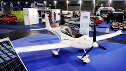
23-4. Elektra One has a maximum power of16-20 kW, and range is more than 400 km (249 miles) with a flight time of up to more than three hours.
The route being followed by Solar Impulse 2 is entirely in the northern hemisphere; its closest approach to the equator was expected to be a flyby of Honolulu at 21.3° N. Twelve stops were originally planned to allow the alternation and rest periods of pilots Borschberg and Piccard, and to ensure good weather conditions for each take-off and landing site along the route. For most of its time airborne, Solar Impulse 2 has been cruising at a ground speed of between 50 and 100 kilometers per hour—usually at the slower end of that range at night to save power. The legs of the flight crossing the Pacific and Atlantic oceans are the longest stages of the circumnavigation, and were each expected to take about five days. On multi-day flights, the pilots take 20-minute naps and use Yoga or other exercises to promote blood flow and maintain alertness.
By the end of May 2015, the plane had traversed Asia. It made an unscheduled stop in Japan to await favorable weather over the Pacific, increasing the expected number of legs of the journey to 13. The aircraft began the flight from Japan to Hawaii on June 28, 2015 (June 29, Japan local time). With Borschberg in the cockpit, it reached Hawaii on July 3, setting new records for the world’s longest solar-powered flight both by time (117 hours, 52 minutes) and distance (7,212 km; 4,481 mi). The flight’s duration was also a record for longest solo flight, by time, for any aircraft. During that leg, however, the plane’s batteries were damaged by overheating caused by being packed in too much insulation. New parts had to be ordered, and as it was late in the season, the plane was grounded in Hawaii, and the U.S. Department of Transportation is storing the aircraft in a hangar at Kalaeloa Airport on Oahu.
New batteries have been made and were installed in the plane in the early weeks of 2016. Test flights began in February, and the circumnavigation resumed in April 2016, when northern hemisphere days lengthen enough to permit multi-day solar-powered flights.
Electric Aircraft
For several years, all-electric power assisted gliders and hang gliders have been available. Advantages of electric aircraft include improved maneuverability due to the greater torque from electric motors, increased safety due to decreased chance of mechanical failure, less risk of explosion or fire in the event of a collision, and less noise. There will be environmental and cost benefits associated with the elimination of consumption of fossil fuels and resultant emissions.
Electric aircraft are available from several sources worldwide. As with on-road vehicles, the major problem with electric aircraft is range—the best of both being 160 to 400 km (about 100 to 250 miles) in a practical manned configuration. Following are descriptions of these aircraft.
The battery and solar-panel powered Elektra One (Fig. 23-4) is built of lightweight fiber composite structures. Maximum power is 16-20 kW, and range is more than 400 km (249 miles) with a flight time of up to more than three hours. Its wingspan is 8.6m, and it can carry up to a 90kg payload.
Cri-Cri (Fig. 23-5) uses composite materials instead of metal to reduce overall weight and make room for the high-energy-density lithium batteries that provide power to four brushless electric motors—two mounted back-to-back on nose pods on each side—with counter-rotating propellers. Projected performance is 30 minutes of cruise flight at 110 km/h (68 mph); 15 minutes of full aerobatics at up to 250 km/h (155 mph); and a climb rate of approximately 5.3 m/sec (1,020 fpm.
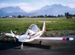
23-5. Cri-Cri uses composite materials instead of metal to reduce overall weight and make room for the high-energy-density lithium batteries that provide power to four brushless electric motors —two mounted back-to-back on nose pods on each side—with counter-rotating propellers.
Yuneec’s E430 (Fig. 23-6) is a two-seat, V-tailed, composite aircraft with a high-aspect ratio wing. Take-off speed is 40 mph, cruise speed is 60 mph, and max speed is 95 mph. The company claims that the battery packs have an expected lifespan of 1,500 hours and cost $7,000 each, with the aircraft carrying three to five battery packs, giving two to two and half hours endurance. The batteries can be recharged in three to four hours from a 220V outlet.
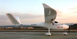
23-6. The E430 uses three lithium polymer battery packs that allow it to fly for two hours in an “optimum cruise” with two people on board.
Sonex is the prototype of a Waiex E-Flight Electric-powered plane resulting from a partnership between Sonex Aircraft LLC and AeroConversions. This electric plane (Fig. 23-7) will use a dc cobalt motor, controller, and highly efficient battery and charging system. The emphasis will be placed solely on power-plant research and development to develop an efficient sturdy and efficient power system.
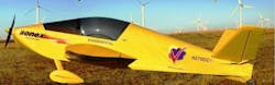
23-7. The Sonex electric airplane will use a dc cobalt motor, controller, and highly efficient battery and charging system. It will emphasize power-plant research and development.
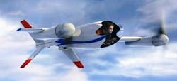
The Puffin is a vertical-takeoff and landing aircraft, taking off like a helicopter and flying like a plane. Just 60 horsepower gets pilot and craft airborne. It is 12 feet high with a 13.5-feet wingspan and its rotors are nearly 7.5 feet in diameter. Rather than tilting the rotors forward for horizontal flight, the whole craft, cockpit and all, pitches forward, so the pilot flies from a prone position. During takeoff and landing, the tail splits into four legs that serve as landing gear, and flaps on the wings deploy to keep the aircraft stable as it lifts and descends. It can cruise at 150 miles per hour and sprint at more like 300 miles per hour. Its range is 50 miles, which is related to its battery density. Using carbon composite construction, the Puffin weighs less than 400 pounds including the lithium phosphate batteries. Fig. 23-8 shows the Puffin parked in its vertical position and Fig. 23-9 shows the Puffin in flight.
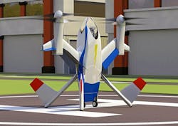
23-8. The Puffin is a vertical-takeoff and landing aircraft, taking off like a helicopter and flying like a plane. It uses carbon composite construction and weighs less than 400 pounds, including the lithium phosphate batteries. It is shown parked in its vertical position.
23-10. AeroVironment’s Puma battery-powered unmanned aircraft.
The Puma AE is durable with a reinforced fuselage construction, portable for ease of mobility, and requires no auxiliary equipment for launch or recovery operations. The system is quiet to avoid detection and operates autonomously, providing persistent intelligence, surveillance, reconnaissance, and targeting data (ISRT).
The Puma AE delivers 3.5-plus hours of flight endurance, with versatile smart-battery options to support diverse mission requirements. Its powerful propulsion system and aerodynamic design make it efficient and easy to launch, especially in high altitudes and hotter climates. A plug-and-play power adapter is provided for easy integration of future extended endurance options, such as, solar and fuel cell solutions.
It carries both an electro-optical (EO) and infrared (IR) camera plus illuminator on a lightweight mechanical gimbaled payload, allowing the operator to keep “eyes on target.” For increased payload capacity, an optional under-wing Transit Bay is available for easy integration of third-party payloads such as communications relay, geo locations, or laser marker to meet the diverse needs of military or civilian applications.
The precision navigation system with secondary GPS provides greater positional accuracy and reliability of the Puma AE. The UAV is operated from AeroVironment’s battle-proven ground control station (GCS) with a communications range of 15 km. The GCS allows the operator to control the aircraft manually or program it for GPS-based autonomous navigation.
Solar-Powered Ship Travels the World
The MS Tûranor PlanetSolar, the world’s largest solar-powered boat (Fig. 23-11), was the first boat to circumnavigate the world powered exclusively using solar energy. It docked on May 4, 2012, after sailing for 584 days and traveling over 60,000 km.
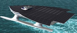
23-11. MS Tûranor PlanetSolar, the world’s largest solar-powered boat.
This initial version of the solar boat is a 31-meter three-hull catamaran. Its deck has over 500 square meters of 18.8% efficient solar panels rated 93 kW. Panels charge 648 series and parallel connected lithium-ion batteries that produce 388 V and 2910 Ah. The batteries power two 10kW (maximum), 1000 rpm permanent magnet synchronous motors in each hull. The boat’s shape allows it to reach speeds up to 14 knots. Its carbon-fiber composite hull was model tested in wind tun¬nels and was tank tested to determine its hydrodynamics and aerodynamics. Construction cost was 12.5 million euros. Its name, derived from J.R.R. Tolkien’s novel The Lord of the Rings, translates to “The Power of the Sun.”
Its two years of solar circumnavigation were instructive for PlanetSolar and led to an initial assessment of the vessel’s performance. This assessment indicated where optimizations were needed to make the boat more efficient and maneu¬verable. These improvements will expand and diversify the boat’s applications and uses; notably, enabling it to navigate to the northernmost part of the Atlantic, near the Arctic, for the first time.
The ship recently went to sea with a team of scientists who will monitor the air and water of the Atlantic Ocean’s Gulf Stream, a current that influences the climates of North America’s east coast and Europe’s west. The team of scientists will monitor ocean phenomena such as eddies and whirlpools that, in the right environment, help to power the so-called ocean conveyor belt that drives circulation in the oceans.
This new four-month scientific expedition will take the Tûranor out of the Mediterranean headed toward Miami, Fla., at the southwestern tip of the Gulf Stream. From there, physicists, biologists, and climatologists from the University of Geneva, led by Professor Martin Beniston, director of the Institute of Environmental Sciences at the university, will begin continuous monitoring of the air and water in a project dubbed PlanetSolar Deep Water.
Built in Kiel, Germany, the catamaran runs exclusively on solar energy. After two years of design and construction, PlanetSolar was responsible for many technological advances, notably in the domain of com¬posite material manufacturing and solar energy storage.
In preparation for its 2013 expedition, the MS Tûranor PlanetSolar underwent major maintenance upgrades. Among the extensive maintenance tasks and optimizations car¬ried out, most notable was the cabin refurbishment, the creation of a walkway on the solar bridge, an increase in water tank capacity, and improve¬ment to the rudder. The most significant optimization was a change to the propulsion system—replacing the surface propellers with a completely immerged system.
This project is under the direction of the University of Geneva, Switzerland. Founded in 1559, the University of Geneva (UNIGE) ranks among the top 100 universities in the world. UNIGE welcomes approximately 16,000 stu¬dents each year to its eight colleges, dealing with the essen¬tial domains of science, medicine, literature, economic and social sciences, law, theology, psychology, education, transla¬tion, and interpretation sciences.
U.S. Navy’s DDG 1000 Incorporates an Integrated Power System
The future USS Zumwalt (DDG 1000) has begun sea trials in the Atlantic Ocean (Fig. 23-12). The largest destroyer ever built for the U.S. Navy and the first of three Zumwalt-class destroyers, DDG 1000 will be the first U.S. Navy surface combatant to employ an integrated power system (IPS) to generate the total ship electric power requirements, then distribute and convert it for all ship loads from common gas turbine generators. This power flexibility allows for potentially significant energy savings and is well suited to enable future high-energy weapons and sensors. The IPS is a unique design integrating a power system with fight-through power and allowing automatic reconfiguration if there is damage to the power distribution system.
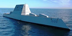
23-12. The U. S. Navy’s DDG-1000 has an integrated power system with an all-electric architecture that provides electric power to the total ship (propulsion and ship service) with an integrated plant.
Integrated Power System (IPS)
An integrated power system is an all-electric architecture that provides electric power to the total ship (propulsion and ship service) with an integrated plant. IPS enables a ship’s electrical loads, such as pumps and lighting, to be powered from the same electrical source as the propulsion system (e.g., electric drive). This eliminates the need for separate power-generation capabilities for these loads. In commercial applications, this is known as the “power station” concept.
Anticipated benefits of IPS include:
• Fewer prime movers: Usually allows a reduction from a total of seven to five prime movers in the traditional gas-turbine surface combatant.
• Reduced costs of ownership: Results in significant fuel savings (15%-19% in a typical gas-turbine combatant). Fewer engines installed results in less maintenance and manning.
• Naval architectural flexibility: Provides flexibility in locating prime movers, allowing space previously used for uptakes to be put to better use.
• Improved survivability and stealth: Quiet propulsion motors can better meet current acoustic requirements. Smaller main machinery spaces allow for improved damage control.
• Improved warfighting: Integrated power makes large amounts of power available throughout the life of the ship. This power can be reallocated to accommodate future combat systems. Advances in power conversion are making it possible to provide uninterrupted power, advanced fault isolation, and fight-through capabilities beyond what is currently available.
In a typical mechanical-drive propulsion system, the propulsion prime movers are connected to long shafts running through the ship to large reduction gears that rotate the ship’s propellers. With electric drive, the prime movers rotate electric generators that are connected through cabling to motor drives and electric motors that rotate a ship’s propellers. Electricity is the medium for transmitting the energy of the prime mover. It enables “cross connecting” of any available prime mover/generator combination by breaking the physical link between the power-generation and power-utilization components.
IPS provides for all of a ship’s electrical needs, including propulsion and ship service loads. Traditional electric drives only provide for propulsion. They do not include power for ship service loads.
The Navy has used electric drive in many ships, including early aircraft carriers, a number of ships during World War II, and many of the current inventory of smaller auxiliary ships. In fact, the Navy is leveraging as much as possible from the cruise-ship industry, where nearly all new ships employ integrated electric systems. What is new and significant is the application of these concepts in a fully electrically integrated (no mechanical takeoffs for power) power system on a surface combatant. These ships have higher speed and lower noise requirements than any of the other ships, as well as large combat systems to support. Commercial cruise ships would be too big and too noisy for a surface combatant, and do not have a power-system architecture to let them survive damage and continue to fight.
Training Required
The new crew trained on components including main and auxiliary turbine generators, propulsion motors and drives, dynamic braking resistors, auxiliary control panels, and high-voltage switchboards. They also spent time working with harmonic filters, neutral ground resistors, the Integrated Fight-Through Power System (IFTP), power conversion modules, and an emergency diesel generator.
Equipment operation was conducted at the local control level, as well as the remote supervisory Engineering Control System (ECS). The ECS system provides a significant advancement in machinery control with automation for system transitions and power management to support the reduced manning concept for the DDG 1000.
DDG 1000’s power allocation flexibility allows for potentially significant energy savings and is well-suited to enable future high-energy weapons and sensors.
Its wave-piercing Tumblehome ship design has provided a wide array of advancements. The composite superstructure significantly reduces cross-section and acoustic output, making the ship harder to detect by enemies at sea. The design also allows for optimal manning with a standard crew size of 158 sailors (including air detachment), thereby decreasing lifecycle operations and support costs.
DDG 1000 will employ active and passive sensors and a Multi-Function Radar (MFR) capable of conducting area air surveillance, including over-land, throughout the extremely difficult and cluttered sea-land interface.
Read more articles from the Power Management Series in the Power Management section of our Series Library.
About the Author

Sam Davis
Sam Davis was the editor-in-chief of Power Electronics Technology magazine and website that is now part of Electronic Design. He has 18 years experience in electronic engineering design and management, six years in public relations and 25 years as a trade press editor. He holds a BSEE from Case-Western Reserve University, and did graduate work at the same school and UCLA. Sam was the editor for PCIM, the predecessor to Power Electronics Technology, from 1984 to 2004. His engineering experience includes circuit and system design for Litton Systems, Bunker-Ramo, Rocketdyne, and Clevite Corporation.. Design tasks included analog circuits, display systems, power supplies, underwater ordnance systems, and test systems. He also served as a program manager for a Litton Systems Navy program.
Sam is the author of Computer Data Displays, a book published by Prentice-Hall in the U.S. and Japan in 1969. He is also a recipient of the Jesse Neal Award for trade press editorial excellence, and has one patent for naval ship construction that simplifies electronic system integration.
You can also check out his Power Electronics blog.
Comment About the Article
To join the conversation, and become an exclusive member of Electronic Design, create an account today!

Leaders relevant to this article: