How Does Power Factor Correction Impact Your Utility Bill?

This article is part of the Power Management Series: What’s the Difference Between Watts, RMS, and More?
Download this article in PDF format.
Your utility Power Factor is the ratio of the system’s Real Power and the Apparent Power (Eq. 1, Fig. 1). This unitless factor ranges from −1 to 1. The Power Factor ratio aptly describes the type of storage elements in the circuit and the phase relationship of the current to voltage. More importantly, for utility companies, this ratio provides insight into a user’s power consumption habits, enabling them to apply fees related to lower value Power Factors (usually below 0.80 or 0.85).
Power Factor = Real Power/Apparent Power (1)
Inductive or motor-control environments are most apt to impact the system’s Power Factor. Consequently, many industrial processing facilities are piquing the interest of utility companies due to their typically low Power Factor numbers. These facilities have a large number of induction motors that drive pumps, conveyors, and other machinery in the plant. Induction motors, with their inductive elements, cause low positive Power Factors.
Power Factor
The three elements of the Power Factor diagram are Real Power, Reactive Power, and Apparent Power. In Figure 1, the graphical relationship of these powers conveniently uses a right triangle, where the Pythagorean theorem of S2 = P2 + Q2 becomes very helpful.
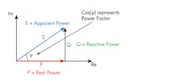
1. The “power triangle” includes Real Power, Reactive Power, and Apparent Power.
A wattmeter measures Real Power (P) (also known as Working Power, Actual Power, or Active Power), providing a value with units equal to watts (W). The Real Power or P actually powers the equipment that performs useful work.
The Apparent Power (S) measurement is equally simple to perform. For the S value (Eq. 3), multiply the total voltage by the total current to provide a value with units equal to VA. The Apparent Power or S is the “vectorial summation” of Real Power (S) and Reactive Power (Q).
The Reactive Power (Q) derivation uses the P and S in the Pythagorean theorem (Eq. 2). The Q units are equal to VAR (Volt Ampere Reactive). With a positive Power Factor value, Q is the power that magnetic equipment (transformer, motor, and relay) needs to produce the magnetizing flux. With a negative Power Factor value (Eq. 4), Q is the power that a capacitive element needs to produce an electric field.

To help illustrate these points further, Figure 2 shows a 240-V ac model driving an inductive load. In the figure, V = 240 Vrms; I = 9.515 Arms; and P = 2.0 kW.
S = V × I = 240 V × 9.515 Arms = 2.284 kA (3)
Power Factor = P / S = 2.0 kW / 2.284 kVA = 0.88 (4)
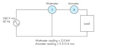
2. A 240-V ac model drivies an inductive load. the wattmeter measures the total Real Power of the system and the ammeter measures real-time system current.
As discussed earlier, the industrial processing facilities run the risk of running a facility with low Power Factor values. In turn, many electric utility companies acquire a low Power Factor penalty. This incentive drives factories to design-in higher Power Factors by adding power-factor-correction (PFC) elements.
Power Factor Correction
The key contributors to Power Factor reduction are transformers, induction motors, induction generators (windmill generators), and high-intensity discharge (HID) lighting. To battle the facility’s low Power Factor values, there are reactive power elements that increase Power Factor, including capacitors, synchronous generators (utility and emergency), and synchronous motors.
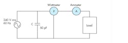
3. This circuit with power factor correction uses a 50-pF capacitor.
An electric motor load creates a lagging (inductive) or positive Power Factor. Typically, installed capacitors decrease the magnitude of the net Reactive Power (VAR), thereby increasing the Power Factor. The correct capacitor of appropriate size, wired in parallel, solves the low Power Factor problem (Fig. 3). We will use the Reactive Power value to calculate the capacitor size (Eqs. 5 and 6):


where Q = Reactive Power; V = system supply voltage = 240 Vrms; XC = capacitive reactance agent; f = system frequency (60 Hz); and C = new capacitor in farads.
From Equation 5, XC = 52.26 Ω, and from Equation 6, C = 50.7579 μF or 50 μF.
Low Power Factors
Power Factor challengers claim that there’s no system penalty for low Power Factors. This may be true to a point for a typical home power user who may never see the impact of a low Power Factor regarding increases in electrical bills or home electronic performance. There’s no benefit for such users in terms of PFC. For the utility and industrial users, this claim is markedly not true.
A low Power Factor indicates an imbalance that manifests itself as a phase shift between the voltage and current signals in a power supply. This may or may not be an issue. However, it’s possible that the power supply may dip, and for the heavy motor user, the utility company may not respond in kind.
Read more from the Power Management Series: What’s the Difference Between Watts, RMS, and More?

About the Author
Comment About the Article
To join the conversation, and become an exclusive member of Electronic Design, create an account today!

Leaders relevant to this article: