Simple, Low-Cost Dynamometer Setup for Motor Testing (Part 2)
Download this article in PDF format.
In Part 1, I overviewed the technical details that impacted the design decisions for the dynamometer. In this article, I describe the final dynamometer system that the students on the Motor Torque Test Bench team (MTTB) built for me.
The Solution
Figure 1 shows a block diagram of the dynamometer’s architecture. Table 1 describes each of the dynamometer components with the reasons for selection.
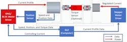
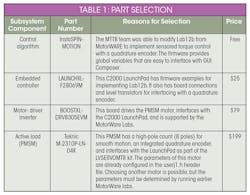
The total cost of the main components of the dynamometer is almost USD $303. This doesn’t include the aluminum frame for mounting the motors, hardware, and machining costs (USD $140 material costs + USD $413 machining labor costs).
Initial GUI and Firmware—Speed Control
Chris Clearman’s article and the advice he gave me offline helped the MTTB team decide on the hardware setup. The team and I experimented with the InstaSPIN-MOTION firmware as Chris recommends in the article. Using the Lab12b firmware example from MotorWare, I made an initial GUI (graphic user interface) for the dynamometer (Fig. 2).
I created a new GUI Composer project (myTI login required) following the steps for MSP432 XDS interface (more helpful GUI Composer information on the “Getting Started” page). I bound the indicators and controls to the following variables required by Lab12b. The “.$q24” addition on the end of the variable name helps GUI Composer to display IQ-math variable types correctly. Otherwise, it would interpret them as a “long” and the values would not make sense. Table 2 shows how I bound the variables to the controls and describes the function of each control.
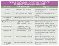
Figure 3 depicts the block diagram structure of the Lab12b code. The SpinTAC algorithm works to regulate the speed of the motor based on the encoder’s signals. If an external torque begins to slow the motor, the SpinTAC controller increases the iq current (same as Iqsr from Equation 3 from the first article) in order to boost the PMSM torque.
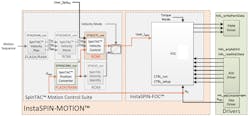
Following Chris’s blog, Lab 12b can implement a basic dynamometer by setting the negative and positive iq bounds to a current level that produces the desired torque when the speed reference is 0 kRPM. As the motor under test (MUT) spins the PMSM, the SpinTAC controller increases the iq current (and therefore, the torque) to try to bring the rotor speed back to 0 kRPM. Eventually, the error in the SpinTAC loop increases to a point where the required iq current is at its positive or negative limit. This worked great for initial testing, but it requires more modifications to fully control the torque.
The next step was to modify the Lab 12b firmware to remove the speed-control loop. I did this by disabling the SpinTAC loop and modifying Lab 12b using some of the instructions in Motorware Lab 4. Lab 4 implements a torque-control loop, but it doesn’t use an encoder, which is why I stuck with the Lab 12b code. All of the necessary modifications can be done within the proj_lab12b.c file.
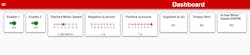
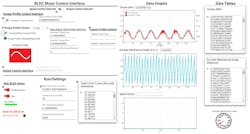
The University of Texas at Dallas (UTD) team further modified the firmware to implement torque profiles and data collection in the GUI Composer. Figure 4 shows the GUI they created. It reports torque, mechanical angle, speed and a timing reference. In addition, it allows the user to select speed control, torque control, and torque profiles.
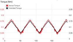
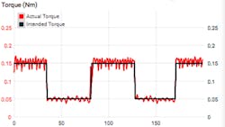
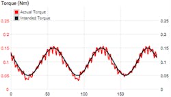
Figures 5-7 show the plots for the configurable torque profiles with the estimated motor torque.
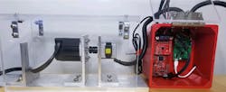
The UTD students documented their project on the TI University hackster.io page. Their GUI and firmware are both available there for reuse. Figure 8 shows the final fully-assembled dynamometer system testing a stepper motor.
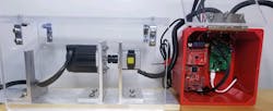
The dc power-supply rails of the stepper-motor driver board and the DRV8305 BoosterPack (PMSM driver board) are connected together on the same power supply. This allows the power to recirculate between the PMSM and stepper when the PMSM goes into its generator region. Otherwise, the power from the PMSM would need to be dissipated some other way, like adding an external load.
Conclusion
At the end of our eight-month journey, the MTTB team truly impressed me with their accomplishments. We all learned an incredible amount about different motor types, motor construction, and motor control. We carefully thought through many design concerns, and I now have an excellent dynamometer to use for motor testing.
For future development, I would like to enable an option to interface the dynamometer with LabView and add a feature that allows me to drive the motor under test (MUT) to a stall condition without overdriving it. I would also check out the new C2000WARE-MOTORCONTROL-SDK, which released toward the end of our project.
James Lockridge is a systems engineer within TI’s motor-drives business.
Acknowledgements
- University of Texas at Dallas UTDesign staff and students (listed as contributors on the Hackster page)
- Chris Clearman for recommending the LaunchPad, BoosterPack, and InstaSPIN firmware to get us started on development.
- David Magee, Rajan Narasimha, and Stephen Fedigan for our discussions on dynamometer designs earlier in the project.
Resources
Acarnley, Paul P. Stepping motors: a guide to theory and practice. 4th ed., Institution of Engineering and Technology, 2007.
Krause, P. Wasynczuk, O. Pekarek, S. Electromechanical Motion Devices. IEEE. 2012.
“Hysteresis Brakes and Clutches.” 2nd edition. www.magtrol.com. November 2011.
“Understanding the Distinctions Among Torque Ripple, Cogging Torque, and Detent.” Tech Papers. Motion Control Resources. www.motioncontrolonline.org. 15 August 2013.
Akin, B. Bhardwaj, M. Warriner, J. “Trapezoidal Control of BLDC Motors Using Hall Effect Sensors.” www.ti.com. April 2011.