Making Sense of MOSFET On-Resistance Comparisons
What you'll learn:
- The impact of on-resistance on MOSFETs.
- The role of temperature coefficient in comparing different MOSFETs' on-resistance.
- What type of FET has the lowest conduction losses?
There's nothing quite like comparing datasheet specifications for similar devices to increase your frustration levels. It would be so much easier if you could compare on a like-for-like basis, but the reality is that it's hard to achieve.
Take the switch on-resistance (RDS(ON)) of a silicon MOSFET device, for example. This attribute is an essential aspect of selecting a power switching device for power-conversion applications. Switching and conversion losses directly affect overall operating efficiency and are the sum of many small factors. The RDS(ON) characteristics of a MOSFET will have a significant impact on these losses.
An accurate comparison between a silicon MOSFET and a silicon-carbide (SiC) MOSFET, for instance, requires strict attention to the datasheet parameters. The parts under scrutiny need to use the same package format, have the same voltage rating with the recommended gate-drive level, operate at the same junction temperature, and have the same drain current.
Process Technologies and On-Resistance in Context
Several competing process technologies exist for applications requiring hundreds of volts, with Si MOSFETs, SiC MOSFETs, and SiC FETs being the primary candidates. The device datasheets all quote the RDS(ON) characteristic at a given voltage rating, gate-drive voltage, and junction temperature.
Take a part with the on-resistance values quoted with a VGS of 12 V for junction temperatures (Tj) from +25 to + 175°C, with a 20-A drain current. With this information, it’s possible to calculate the temperature coefficient of RDS(ON) for the device. The temperature coefficient is essentially the RDS(ON) characteristic slope, indicating how the on-resistance increases with temperature and is always positive. For this part, at a Tj of 125°C, the temperature coefficient is approximate +70% to 75%.
The Hidden Factors of a SiC MOSFET's RDS(ON) Tempco
If you compare other devices based on their RDS(ON) temperature coefficient, it would be easy to assume, for example, a 650-V SiC MOSFET device with a +20%-25% at Tj 125°C value is a much better part because it’s a factor of three better than the SiC FET. However, this isn’t the case, with the lower coefficient highlighting more underlying issues within the SiC MOSFET.
Within single-carrier MOSFETs and JFETs, the electron flow passes through different regions (Fig. 1). The regions include the substrate, JFET region, drift layer, and the inversion channel.
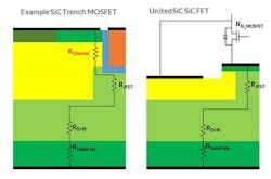
In a 650-V SiC MOSFET, the total resistance is mostly represented by the inversion channel, and this resistance reduces with temperature. Furthermore, the threshold voltage also decreases with temperature. The resistance of other device regions—JFET, drift layer, and substrate—exhibit a positive temperature coefficient, offsetting the negative impact to yield a small positive coefficient value.
It should be noted that a positive temperature coefficient is required for healthy cell operation on the die by promoting current sharing without creating hot spots and thermal runaway.
A SiC FET Has Lower Total Conduction Losses Despite a Higher Tempco
Within a SiC FET, there’s no inversion-channel layer—the bulk channel has a >15X better mobility and a positive temperature coefficient. Without the negative temperature coefficient associated with this region in a SiC MOSFET, by comparison, the SiC FET starts at a low resistance value but increases faster with temperature. That’s because it approaches the ideal resistance behavior of the voltage-supporting drift region.
Figure 2 illustrates the specific on-resistance (per unit chip area) values for a wide range of junction temperatures for a 650-V SiC MOSFET and a 750-V FET. The RDS(ON) scale has been normalized to the 750-V FET’s on-resistance value at a Tj of 25°C.
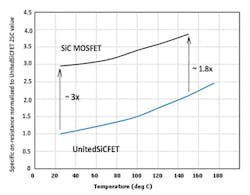
The RDS(ON) of the SiC FET device is a third of the SiC MOSFET at Tj = 25°C and is still almost twice as good at 150°C—and with 50% of the conduction losses for the same die area.
The healthy, positive on-resistance temperature coefficient exhibited by a SiC FET provides efficient current sharing, an essential attribute for paralleled devices, and highlights the lower overall conduction losses for a given chip size.
Before embarking on comparing devices using datasheet specifications, ensure the methods and mechanisms behind the key criteria are well understood. With this approach, an informed and practical device selection can be made. If necessary, base the selection on the behavior of the FETs at target elevated temperatures required in your application.