Heat Sinking to Improve Power Density
This article is part of the Power Management Series: Delving Into Power Density
Members can download this article in PDF format.
What you'll learn:
- How to lower thermal resistance.
- A look at conduction and two forms of convection.
- The importance of fin efficiency.
Today’s electronic power architectures demand high power density even in the presence of increased heat generated by various devices in these designs. The challenge is to cool those devices with a cost-efficient component known as the heat sink. Creating an optimally designed heat sink will improve a power supply’s power density, device reliability, performance, and service life.
Power density is defined as the ratio of power-converter output power to converter volume. This is an important parameter characterizing the compactness of power electronic systems.
The Heat Sink
Thermal issues are a major cause of failure in electronic systems. The temperature of the design environment will directly affect electronic device lifetime. A heat sink is an important component in an electronic design that will enhance heat dissipation from electronic devices, especially for those known as wide-bandgap (WBG) devices, MOSFETs, IGBTs, and other power integrated circuits. Linear and switch-mode power supplies (SMPS) will typically use heat sinks to maintain a safe operating temperature.
The heat-sink base plate transfers heat to the heat-sink fins, which in turn transfer that heat to the lower-temperature air surrounding the electronic design.
Heat sinks have a downside: They expand surface area on circuit boards and increase airflow pressure drop, which reduces the volume of airflow across the entire circuit landscape and thus lowers the heat-transfer coefficient. The maximum allowable junction temperature TJMAX is a prime contributor that will limit the power-dissipation quality of a device. Reference 1 discusses the details of how to properly design a heat sink for a particular dissipation limit.
Lowering Thermal Resistance
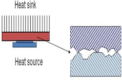
The thermal resistance between a semiconductor package and a heat sink can be lowered if designers would reduce the air gap, a significant resistance to heat transfer (Fig. 1).
Thermal grease as well as other thermally conductive compounds, elastomers, adhesive tape, etc. are thermal interface materials (TIM) that will reduce the thermal resistance.
The heat sink’s thermal resistance may also be lowered via the thickness of the heat-sink base plate. A low thickness will affect conductive efficiency, which will aid in the balance of transfer to the heat-sink fins. (Beware: heat-sink fins may reduce air flow pressure; the designer may want to reduce the density of the fins somewhat. See “Fin Efficiency” section below).
Increasing forced airflow can also reduce thermal resistance by directing the forced air to flow through the fins. If there is too large a gap between the heat sink and the top of the enclosure surface, the forced air may bypass the heat sink. Decreasing that gap will help ensure that the forced air flows mostly through the fins.
Improving Power Density with Proper Heat-Sinking Design Techniques
Heat sinks might appear structurally simple. However, the fluid flow through its fin field and the thermal coupling between it and in the surrounding air creates a fairly complex problem.
Achieving improved power density in an electronic design is certainly challenging. Forced-air cooling will help to significantly improve the power density of a design. Let’s take a look at some good thermal-analysis techniques that will assist designers in attaining better power density.
Switching and conduction losses will quickly heat up a device above its “Maximum Junction Temperature" (Tj max). When this happens, performance failure, breakdown, and, ultimately, fire in severe cases will occur. Designers must calculate the temperature of their devices so that they never exceed Tj max and keep that parameter as low as possible. When it comes time for PCB layout, that’s the point at which thermal management must be considered.
Conduction
For improved heat conduction, heat sinks and components should interface with flat, smooth surfaces using thermal grease or TIM. When placing semiconductors on a board, spacing should allow for a uniform power density.
Convection
Convection transfers the heat energy from the hot surface to air, water, etc., which are all moving lower-temperature fluids. Let’s look at two forms of convection:
Natural convection
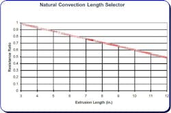
Natural convection is the airflow that’s induced by buoyant forces, which come from different densities, and are caused by temperature variations in a fluid. In a properly designed natural-convection heat sink that’s operating at sea-level conditions, about 70% of the heat is transferred by natural convection and 30% by radiation (Fig.2).
For a heat sink, fin-to-fin spacing should typically be greater than approximately 0.250 inches (6 mm+)
Forced convection
- Forced convection is the air flow caused by external means (e.g. fans, pumps, etc.).
- Heat sinks should have thick fins at a minimum of 0.080 inches (2 mm) or more.
- High fin density should typically be 6 fins/inch, which is a good balance against airflow pressure drop.
- When transitioning from extrusion- to bonded-fins, choose a copper option for applications with very high heat flux.
Forced convection words of wisdom:
- Board-mounted heat sinks need to be staggered to ensure that air flow passes over all fins.
- Never block airflow to heat sinks, such as placing large components or structures in the airflow stream.
- Forced-air cooling must be arranged to follow natural-convection air paths.
- In natural convection, use thin fins of about 0.5 to 0.6 inches thick.
- In forced convection, use thicker fins of about 0.6 to 1 inch thick.
- Add serrated fins to increase surface area and reduce heat-sink thermal resistance (20% to 30% increases can typically be achieved).
Fin Efficiency
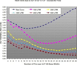
Fin efficiency will increase as the length of the fin decreases, the thickness of the fin increases, the thermal conductivity of the fin increases, and the heat-transfer coefficient decreases (meaning airflow velocity is decreasing). Fin efficiency should be in the 40% to 70% ranges. The number of fins also is very important in a heat sink (Fig. 3).
Beware that as heat-sink temperature delta decreases, the heat-sink efficiency also will drop.
The cooling system contributes significantly to the total volume of the power converter. The theoretical power density of the cooling system (converter output power divided through the converter’s cooling-system volume) indicates one important theoretical limit of the whole converter system’s power density.
A Theoretical Limit for Power Density in Power-Converter Systems
With higher heat-sink temperatures (and especially higher fin surface temperatures), proportionally more heat can be removed via forced convection. The heat-sink fin surface can be reduced, leading to a smaller heat-sink volume and, therefore, higher power density.
Losses increase with higher junction temperatures and will lower system efficiency. Reduced system efficiency leads to higher losses for the same output power level, resulting in the need for a larger cooling system. This will partly offset the beneficial effect of the higher heat-sink temperature.
The use of WBG-based power electronic systems, coupled with advanced cooling techniques, will lead to a high system power density.
To find the theoretical limit of the cooling-system power density of a converter employing forced-air cooling, the heat sink must be carefully optimized in terms of power density.
Natural convection and radiation modes of heat transfer are typically applied cooling techniques for electronic equipment in the low to moderate power-density ranges. These might be computer chips, various electronic designs, and telecommunication boxes. The main advantages of natural convection are high reliability, low noise, and low power consumption.
Air movement in a naturally ventilated cabinet is induced by a pressure difference between the interior and exterior of the cabinet. This pressure difference occurs due to a density gradient in the air, which produces a force that pushes the air upward and out. The thermal design of the electronic equipment must be optimized because of this relatively low airflow efficiency.
To generate airflow that results in the appropriate temperature rise inside the enclosure, special attention must be paid to the geometrical configuration of the heat source and the ventilated enclosure. A cooling-system performance can be defined, which enables direct comparisons of different cooling systems (for example heat sink plus fan), taking into account the power density.
Summary
Heat-sink optimization will help determine the dimensions, weight, and thermal performance to meet power-system design requirements. Finding the optimal number of fins will determine the best solution for temperature at the base of the sink. When the number of fins is increased past an optimal value, the thermal performance of the sink will worsen. This will lead to restricted flow inside the heat-sink U-channels and, eventually, electronic box failure.
The goal is to determine the optimal number of fins to maximize heat transfer. Fin thickness is the major parameter for best heat-sink performance. Although thinner fins increase the optimum number of the fins, they actually decrease the weight of the heat sink and improve the heat sink’s thermal performance.
Optimizing a heat-sink design and employing proper airflow will lead to a more compact cooling system with high heat extraction. System high power density can be achieved with a small-sized, high-power-density power converter coupled with the high cooling capability of the heat sink.
The use of WBG devices in the power-supply architecture will further enhance the overall system power density.
References
1. Understanding Thermal Dissipation and Design of a Heatsink, Application report SLVA462, May 2011
2. AN-2020 Thermal design by insight, not hindsight, April 2013
3. Tech Brief: “Heat sink design facts & guidelines for thermal analysis,” Wakefield-Vette


