Behind the Meter, Energy Storage Finds Its Place
What you'll learn:
- What are the power-handling elements of a behind-the-meter solution?
- Topology approaches to power-conversion system designs.
- Installation approaches to commercial and industrial energy-storage systems.
The market for energy-storage systems (ESS), a key part of the infrastructure for the transition to renewable-energy sources, has reached the inflection point of the classic hockey-stick growth curve in the U.S. Researchers at Wood Mackenzie forecast overall market revenue as tripling in 2021, reaching more than $4 billion, from $1.6 billion last year, and reaching $7 billion in annual revenue by 2025. While much of this growth is in front-of-the-meter, utility-scale storage, the so-called behind-the-meter (BTM) segment also is on track to nearly triple in the next four years, reaching more than $2.5 billion in revenue by 2025.
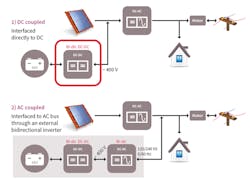
The benefits of local storage include consumer/commercial user cost savings by shifting use from utilities at peak periods and power availability in case of utility service disruptions such as brownout/blackout. Two system approaches, illustrated in Figure 1 (dc-coupled, top, and ac-coupled, bottom), are similar for both consumer and commercial solar installations intended to provide some degree of grid independence, with variations based on the customer requirements. Residential systems are often in the 3- to 5-kW range, and rarely above 10 kW.
Cost and size are important considerations, with reliability and low maintenance/low touch operation as key factors. Commercial buildings may typically be rated at 50 kW or more and multiple units may be in place, which makes load sharing and current balancing among units a requirement for reliability. In both market segments, there’s a clear trend toward paralleling of common building blocks to reach desired capacity.
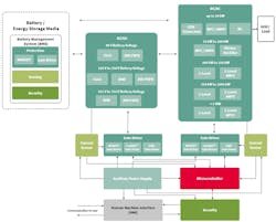
As seen in Figure 2, the power-handling elements of BTM storage solutions are based on several electronic subsystems: the battery-management system (BMS), dc-dc and ac-dc power-conversion systems (PCS), corresponding driver and current-sensing elements, and finally control and security components. This article looks at power conversion, exploring technology approaches for both residential and commercial/light industrial scenarios.
Power-Conversion System Overview
Figure 2 identifies various topology approaches to PCS designs for residential and commercial applications at a range of battery voltage and system power levels. The PCS is bidirectional in nature—a dc charging mode that accepts power from a local solar source, and there’s conversion from dc to ac when delivering power to the load or selling back to grid.
A more detailed diagram (Fig. 3) shows a typical residential system supporting a 48 V Li-ion battery pack. The system is divided into three stages, using variations of the basic H-bridge.
Stage 1 converts battery voltage to high-frequency ac. Using a resonant topology allows for highly efficient zero voltage switching during backup mode, and acts as a synchronous rectifier while in charging mode. 60-V trench MOSFETs with low-power MOSFETs that have low RDS(on) , such as Infineon’s OptiMOS family, and packages with excellent heat dissipation and low parasitic inductance are well-suited for this stage.
For Stage 2, silicon-carbide (SiC) MOSFETs in the 600- to 650-V range have emerged as a preferred choice for high-frequency switching between 400 to 500 V. The advantages of the wide-bandgap MOSFET compared to silicon devices include higher critical breakdown fields, enabling RDS(on) as low as 27 mΩ. Higher thermal conductivity equates to higher current density, while the wide bandgap results in lower leakage current at high temperatures. This means that with equivalent conduction losses, the SiC MOSFET approach can have a higher RDS(on) than a silicon MOSFET solution.
Two alternative approaches for Stage 3 are worth consideration. The system shown in Figure 3 is referred to as a “Highly Efficient and Reliable Inverter Concept” (HERIC), which employs back-to-back switches to convert a pulse-width-modulated (PWM) ac waveform that’s passed through a low-pass output to produce a sine-wave output. During charge mode, the stage operates as a synchronous totem-pole PFC converter that operates in positive and negative line half-cycles to generate high-voltage dc for conversion in the subsequent stages to charge the battery.
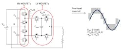
An approach that can reduce size and weight, while improving efficiency and power density, is to use a multilevel inverter topology for Stage 3, such as the five-level active neutral point clamp (ANPC) (Fig. 4). This uses low-voltage trench MOSFET devices with very low RDS(on) and body-diode recovery charge (QRR). Reduced power dissipation of the switches reduces heat sinking, lowers the harmonic content and significantly lowers EMI of the solution. This can justify the higher level of complexity, in both the number of switches and isolated gate drivers, to achieve form factor and efficiency benefits in converters of 3 to 5 kW.
Light Commercial and Industrial ESS
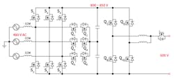
In commercial energy-storage systems with power ratings ranging from 30 ~ 50 kW, performance, size, design complexity, and cost considerations influence the topology and component selection. Figure 5 illustrates a performance-optimized topology using SiC MOSFETs in ac-dc and dc-dc sections. State-of-the art IGBTs also may be used in the ac-dc segment of the topology. For example, TRENCHSTOP 5 H5 series 650-V IGBTs (for Q1-Q6) and TRENCHSTOP 6 series 1200-V IGBTs (for S1-S6) products offer a performance-cost-optimized choice.
On the dc-dc converter, SiC MOSFETs are well-suited for high-frequency switching. SiC modules help reach higher power density, simplicity of design, and thermal performance where higher power ratings and density is sought. For instance, EiceDRIVER gate drivers have several protection features and isolation that facilitate efficient IGBT and SiC switching performance.
Innovation
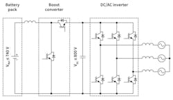
While the system concept for commercial installations is similar to that of residential ESS, the output is connected to three-phase ac, typically at 480 VRMS. Usually, multiple Li-ion battery cells are connected in series, and the resulting battery pack with its integrated BMS has an output of 740 V or more.
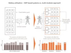
In a typical converter topology for the battery pack (Fig. 6), the system uses discrete IGBTs or IGBT modules rated at 1200 V and connected to an 800- to 900-V bus. However, this straightforward approach is limited in its battery utilization. When battery cells in the series have different states of charge, the minimum allowable charge level of one battery pack sets the operating limit of the entire system. This is a particularly acute problem in system concepts using second-life battery packs from electric vehicles, which are most likely to be in various states of min/max charge history.
A modular, cascaded multilevel architecture overcomes this limitation (Fig. 7). Battery modules made up of bundled cells are connected to individual power converters, and these are linked in series. Multilevel operation is controlled at the system level by a central controller, which may direct power in either series or parallel configurations to step through the different voltage levels of each module and produce approximate full-wave rectified voltage. This is then filtered before passing through a low-frequency stage to produce a clean output for the load or grid.
In such an approach, a typical topology for each module’s power converter is based on an H-bridge using 80- or 100-V trench MOSFET devices with packages optimized for high current capability with low parasitic resistance and inductance. Switching frequency of each module can be below 10 kHz, as the effective output frequency of the system is the product of all modules in the system (minus one).
Conclusion
As noted earlier, and illustrated in Figure 2, multiple topologies exist for both the dc-dc and dc-ac stages of ESS power-conversion systems, depending on voltage of the target battery systems and total power rating of the application. Many factors are involved, such as balancing design complexity with cost and efficiency goals, which determine when it’s most appropriate to use discrete devices or power modules.

