Regulation Loop Without a Resistive Divider (Download)
Power converters typically incorporate a control loop to maintain a set output voltage, irrespective of variations in input voltage or load current.
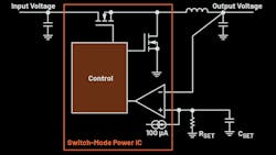
A resistor divider is often used to sense output voltage. Figure 1 shows one example—a step-down converting buck regulator circuit. In this control loop, a resistor divider (RFB1 and RFB2) adjusts the generated output voltage to a level specified by the internal reference voltage (VREF). This reference voltage is commonly set at 1.2, 0.8, or 0.6 V. The error amplifier’s output (operational amplifier in Fig. 1) is then fed into a control block that manages the switching times of the power switches (MOSFETs).
