
The term hot loop is relevant whenever switching regulators and their electromagnetic compatibility (EMC) are involved. This topic especially comes up in the optimization of trace routing on printed circuit boards. But what exactly does a hot loop refer to?
Currents are always switched in switching regulators, and they’re usually relatively high. Whenever a current flows, it generates a magnetic field. If high currents are rapidly switched, an alternating magnetic field is generated. Also, if currents are switched through a certain parasitic trace inductance, it creates a voltage offset. The current can capacitively couple into adjacent circuit parts and increase the noise radiation of a power supply. In summary, we can state that the main cause of noise in a switched-mode power supply are the switched currents.
Figure 1 shows a simple buck-converter topology. All lines carrying a continuous current are shown in blue, while all lines that rapidly switch currents are shown in red.
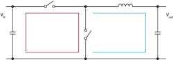
The red paths in Figure 1 are the critical paths. They look like a current loop and are hence referred to as a loop. Hot loop means that this loop is especially critical because it involves rapidly switching currents.
If we take a closer look at this loop, we can see that the red loop in Figure 1 never has any real current flowing since both switches are never turned on at the same time. It’s only a combination of individual lines through which current flows at certain times and no current flows at other times. In Figure 2, arrows showing the direction of current flow are added to the individual connecting lines. Also, symbols showing at which time in a period current flows are given. At other times, no current flows through the conductor.
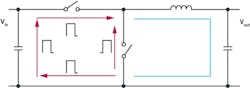
The table reveals when each red trace in Figure 2 conducts—and doesn’t conduct—current. During the on-time of the buck regulator duty cycle, the high-side switch is on, the low-side switch is off, and we see the current flow from the input capacitor, through the high-side switch, but no current flows through the low-side switch. During the duty cycle’s off-time, we see current through the low-side switch (from ground to the switch node) and no current in the other three red traces.

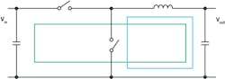
It can easily be seen in Figure 2 that a hot loop isn’t an independent current loop. Rather, it’s only a virtual current loop composed of the components of two real current loops.
Figure 3 shows the real current loops on which the circuit is based. One current loop is shown in blue and another is shown in green. Switching back and forth between these complete current loops does occur. In some paths, however, the currents flow in the same direction in both current loops. Thus, they’re superimposed to form a continuous current and thus aren’t critical as far as EMC is concerned. These traces aren’t referred to as hot loops.
The hot loops in switching regulators differ depending on the switching regulator topology. They should be designed to be as narrow and compact as possible to minimize the noise generated as well as its transmission. The Silent Switcher 2 technology from Analog Devices makes the critical hot loops as small as possible through the integration of input capacitors in the IC package. Likewise, by splitting the hot loop into two symmetrical shapes, two magnetic fields of opposite polarities are created and the radiated noise cancels itself out to a great extent. An example of a switching regulator with this technology is the LT8609S from Power by Linear.
Frederik Dostal is a Field Applications Engineer for power management at Analog Devices.
About the Author

Frederik Dostal
Power-Management Technical Expert
Frederik Dostal is a power-management expert with more than 20 years of experience in this industry. After his studies of microelectronics at the University of Erlangen, Germany, he joined National Semiconductor in 2001, where he worked as a field applications engineer, gaining a lot of experience in implementing power-management solutions in customer projects. During his time at National, he also spent four years in Phoenix, Arizona (USA), working on switch-mode power supplies as an applications engineer.
In 2009, he joined Analog Devices, where since then he held a variety of positions working for the product line and European technical support, and currently brings in his broad design and application knowledge as a power-management expert. Frederik works in the ADI office in Munich, Germany.
Also check out my:
Comment About the Article
To join the conversation, and become an exclusive member of Electronic Design, create an account today!

Leaders relevant to this article: