How to Build Wide-Dynamic-Range Systems (Part 2)

Members can download this article in PDF format.
What you'll learn:
- Comparing two different wide-dynamic-range receivers via simulation.
- How does the pulse signal impact dynamic range?
- Assessing test results of linear vs. multichannel receivers.
- Applications for multichannel receivers.
For Part 1, click here.
The dynamic range of receiver devices is an important parameter that determines their ability to receive and process signals of varying power levels. Wide dynamic range is crucial in many fields, such as wireless communication systems, medical imaging devices, radar systems, and various probing systems. In practice, detecting weak signals amidst strong interference or noise is often necessary, which also requires a wide dynamic range.
In this article, a comparative analysis is performed of an approach that enhances resolution and suppresses impulse interference. It also discusses some practical application options for implementing this approach.
Simulation of Receiver Devices with a Wide Dynamic Range
To compare receiver device characteristics, we created two models: a classical linear receiver and a multichannel analog-to-digital-converter (ADC)-based receiver. Figure 1 shows the structural diagrams for both. We assumed a dynamic range of 96 dB, which corresponds to a 16-bit ADC, for both models, making them easier to understand and implement.
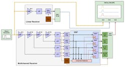
The models operate in the following way:
- The generator produces signals of various shapes, frequencies, and amplitudes, which are simultaneously fed to linear and multichannel receivers.
- The linear receiver operates according to the classical scheme and does not require further explanation.
- The multichannel receiver has a dynamic range divided into four subranges so that each subsequent ADC, starting from the ADC1, is more sensitive than the previous one. This is achieved through a multi-stage connection of amplifiers, where the output of each amplifier is fed to the corresponding ADC channel.
For this scheme, it’s crucial that the amplifiers have a small saturation region and exhibit characteristics similar to an ideal limiting amplifier. ADC1 processes the most powerful signals with voltages ranging from Umax to Umax/16, while the other ADCs are in an overflow state.
If the signal is in the range from Umax/16 to Umax/256, ADC2 is active. If it falls within the range from Umax/256 to Umax/4096, ADC3 is active. Finally, if the signal falls within the range from Umax/4096 to Umax/65536, ADC4 becomes active.
Depending on the signal level, the channel selector chooses only one ADC and passes its data through the enabled buffer corresponding to its group of digital-to-analog converter (DAC) bits. At the same time, the remaining channel buffers are disabled.
Analysis of the Pulse Signal’s Influence
When operating in a wide dynamic range or under conditions of significant interference, the resolution time becomes one of the measures of the system overload capacity. The resolution, in this case, is understood as the time interval between strong interference and a weak signal, when the latter is no longer suppressed.
Figure 2 shows the amplitude-scaled waveform. The original signal highlighted in yellow consists of two pulses with significantly different amplitudes.
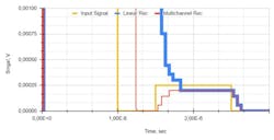
The output signal of the linear receiver is shown in blue. It’s noticeable that the weak signal can’t be distinguished from the strong background pulse because it’s been suppressed. The red color represents the output signal of the multichannel receiver, where no suppression occurred. Therefore, the resolution capability of the multichannel receiver is higher. What’s the reason for the effectiveness of the multichannel receiver?
According to the monograph of Iliin and Poliskij “Dynamic range and accuracy of radioelectronic and optoelectronic measuring systems,” the resolution time of a measuring system is related to the dynamic range and relative measurement error as follows:
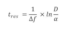
where Δ𝑓 is the bandwidth of the measuring amplifier, D is the dynamic range, and α is the relative measurement error.
Thus, if the relative measurement error is constant, the resolution time of the system can be reduced either by expanding the bandwidth or by reducing the dynamic range. That’s exactly what we achieve in the multichannel receiver approach.
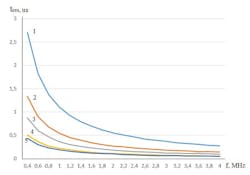
Figure 3 shows the dependencies of resolution time on the bandwidth of the low-pass filter (LPF) for both the linear and the multichannel receiver models with different numbers of channels. Looking at Figure 3, it can be concluded that the resolution capability is higher when the total dynamic range of the receiver is divided among a greater number of channels. This dependency was analyzed by Liutik (“Increasing resolution of wide-range systems,” 2015).
Analysis of the Propagation of Short Impulse Interference Through Receiver Circuits
Pulse noise is a series of random pulses characterized by varying amplitudes, durations, arrival times, and shapes. The impulse interference can significantly exceed the amplitude of the original signal but have much shorter duration.
In communication networks, pulse noise is commonly generated by switching equipment during operation. This phenomenon is particularly prominent in modern multichannel, long-distance communication systems, where pulse noise, along with brief interruptions, can be a major source of errors in the transmission of discrete information.
Let’s consider a sinusoidal signal whose level corresponds to the lower boundary of the receiver's dynamic range (Fig. 4). Chaotic short-duration impulse interference is superimposed on the sinusoidal signal.
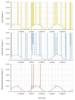
The top diagram in Figure 4 represents the mixture of signals applied to the input of the receiver models. The middle diagram shows the signal from the output of the linear receiver, where the harmonic signal is significantly distorted by the pulse noise. The bottom diagram shows the signal from the output of the multichannel receiver, where the impulse interference is virtually absent. In other words, the multichannel receiver suppresses short-duration impulse interference much better.
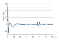
As described earlier, an impulse signal undergoes linear distortions when passing through filtering circuits. These distortions manifest as rounding of the signal edges and peaks. The shorter the duration of the impulse, the more its shape is distorted.
Figure 5 shows the responses to impulse interference of different durations ranging from 100 to 1 ns, as well as the sensitivity thresholds for the linear and multichannel receivers (the sensitivity thresholds are shown for illustrative purposes; in reality, the threshold Umax/65536 should be significantly lower compared to the threshold Umax/16). The receiver detects the signal as long as it remains above the sensitivity threshold of the ADC.
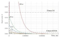
In the considered model, the sensitivity threshold for the linear receiver is Umax/65536, making it susceptible to interference with durations of up to hundreds of picoseconds. In the multichannel receiver, the sensitivity threshold of each channel is significantly lower and equal to Umax/16. Therefore, the multichannel receiver is much less susceptible to pulse noise, which is undoubtedly a significant advantage. A more detailed analysis of impulse noise suppression in receiver devices is described by Liutik ("Suppression of pulse noise in wide-range systems," 2015).
Linear vs. Multichannel Receiver Test Conclusions
Despite having worse performance in terms of root-mean-square measurement error, the model of multichannel receiver provides better resolution with a similar bandwidth. In addition, increasing the number of channels improves the resolution.
By increasing the number of channels in the receiving device to achieve the required measurement accuracy, ADCs with fewer bits are needed. This significantly simplifies the requirements for the ADC printed-circuit-board topology, power-supply cleanliness, and phase-noise level of the clock generator. At the same time, the model of the receiving device based on the principle of the multi-input ADC provides suppression of interference with longer durations while maintaining a similar receiver bandwidth.
Multichannel Receiver Applications
Multichannel receiving devices can be used in areas where measurement accuracy at the upper end of the dynamic range isn’t crucial, while the most important information is concentrated in the lower part. This is particularly applicable in systems heavily saturated with chaotic pulse noise. Such an approach can be effective in the following areas of electronics:
- In radar systems, having a wide dynamic range is important for detecting both distant and nearby targets with high resolution for accurate object identification.
- In medical systems such as magnetic resonance imaging (MRI), computed tomography, and ultrasound, high resolution is required for obtaining precise images. A large dynamic range allows for processing both weak and strong signals, ensuring diagnostic accuracy.
- In digital cameras, a large dynamic range enables the capture of details in both dark and bright areas of the scene, providing high-quality photographs.
- In automotive active safety systems, such as collision warning systems, a wide dynamic range is crucial for accurate object detection and accident prevention.
First and foremost, multichannel receivers can be applied in location probing systems. In such systems, important information may be obscured by large signals.
One possible application is a system for ice monitoring on power transmission lines using a location-based method. It’s designed for early detection of ice deposits on overhead power-line conductors.
The location probing method involves sending an impulse signal into the monitored line and determining the time it takes for the signal to propagate along the conductor in both forward and backward directions after reflection from the end of the line or from inhomogeneities (Fig. 6).
In the ice monitoring system, the impulse interference is the probing signal against which the reflected useful signals need to be detected. Such a system is susceptible to a significant amount of interference from neighboring systems.
Another application could be power profiling devices. A vast number of today’s electronic devices are powered by batteries, including IoT devices; wireless fire, alarm, and smart-home sensors; mobile phones; and tablets. Battery-powered wireless devices often have a complex power profile that strongly depends on the operating mode.
Such devices usually have a low-power sleep mode when the consumption current can drop to tens of nanoamps. At the same time, they may consume current up to hundreds of milliamps in data-transmission mode. Therefore, the dynamic range of consumption currents can easily reach 106 – 107.
To accurately predict the device battery life as well as track issues in the schematics and software that affect consumption, it’s necessary to have a highly accurate power-consumption profile (both in the current and time domains). This requires a current measurement scheme with a wide dynamic range and good time resolution. The approach proposed above allows for meeting both of these requirements.
References
Iliin, G.E., Polskij, J.E. (1989). Dynamic range and accuracy of radio electronic and optoelectronic measuring systems. Results of science and technology. Radiotehnika series. 39, 67-114.
Liutik, K.P., Iliin, G.E. (2015). Increasing resolution of wide-range systems. ISSN 2078-6255. Bulletin of the Kazan State Technical University, 6(82),129-132.
Liutik, K.P., Iliin, G.E. (2015). Suppression of pulse noise in wide-range systems. ISSN 2078-6255. Bulletin of the Kazan State Technical University, 6(82),133-135.
About the Author
Konstantin Liutuk
Konstantin Liutik is an experienced engineer with a strong background in analog and digital electronics, circuits, and PCB design. He has expertise in developing low-power microwave transmitters, receivers, and antenna switches. In addition, he has experience designing high-speed multilayer PCB topologies using Mentor Graphics CAD and signal-integrity analysis tools such as HyperLynx.
Petr Liutuk
Petr Liutik has over a decade of experience developing software for various embedded systems. He started his career by working on wireless fire alarm systems and intelligent home systems based on 802.15.4 and Zigbee technologies. Later, he engaged in software development for a programmable logic controller running on the QNX operating system and implemented CODESYS support. Petr also participated in porting and developing the Linux-based mobile operating system Aurora/Sailfish.
Comment About the Article
To join the conversation, and become an exclusive member of Electronic Design, create an account today!

Leaders relevant to this article: