Tiny Preamplifier Targets Low-Side Current Sensing

What you’ll learn:
- Why low-side current sensing is still widely used.
- Why a precision preamplifier is critical to low-side current-sensing performance.
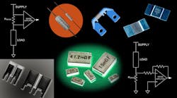
Sensing current flow through a load or from a source is a common, widely needed circuit function. While several contact and non-contact alternatives can accomplish this task, a common choice is to sense the fairly small voltage (typically established to be at around 100 mV) across a known low-value resistor (milliohm values are common) inserted in series.
(Note: Although this is commonly termed a “shunt” resistor, that’s a misnomer, as a true shunt bypasses the load—but we won’t fight that battle here.)
In low-side sensing, the resistor is placed between the load and ground (another misnomer, as it’s usually a circuit common and not a true Earth ground), while in high-side sensing, it’s located between the rail source and the load (Fig. 1). Each approach has well-defined virtues and challenges, which have been discussed in many articles (see "Articles related to current sensing" below).
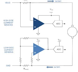
Low-Side vs. High-Side Sensing
With the unavoidable issues surrounding low-side sensing, primarily the implications of not having the load grounded, you might think that high-side sensing is the dominant topology in use—especially in industrial and automotive designs (I assumed that was the case). Perhaps it’s the other way around, though, and high-side sensing gets more attention than low-side sensing because it’s more complicated to implement due to its issues of high common-mode voltage (CMV), the need for level-shifting, and even the need for galvanic isolation in some cases? It’s not clear what the cause and effect is here.
Regardless of causality, the performance of low-side sensing arrangement depends heavily on the precision, stability, and other attributes of the sense resistor and its preamplifier. As the maximum voltage across the resistor is usually quite low while the application is often noisy, the choice of preamplifier is critical to accurate and consistent measurements.
ST’s New Current-Measurement Preamp
Addressing the needs of low-side sensing, the TSC1801 from STMicroelectronics (ST) current-measurement amplifier integrates matched resistors to set the gain (Fig. 2). This isn’t a new development at all, as it simplifies the circuit design, saves bill-of-materials costs, and in this implementation, ensures gain accuracy within 0.15% over the entire temperature range.
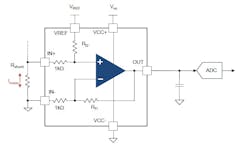
The fixed gain also eliminates production trimming of external resistors, as the initial matching and temperature-drift tracking of these resistors is critical to precision performance. The first gain value offered by ST is 20 V/V, with 5- and 50-V/V models to follow.
The amplifier combines very high accuracy and wide bandwidth, and is well-suited for motor control, solar-power conditioning, high-bandwidth current sensing, and automotive power conditioning. It’s capable of bidirectional current sensing and is optimized for use with precision low-value shunt (sense) resistors at low common-mode voltages. The architecture is dedicated to low-side sensing and features total output error better than 0.5% and offset voltage of ±200 μV (maximum).
The TSC1801’s 2.1-MHz bandwidth rating allows for pulse-by-pulse current control even in very high-frequency power-management systems, translating to tangible benefits such as smoother torque adjustment for lower vibration in motor drives. The amplifier’s fast response also ensures rapid overcurrent detection, protecting sensitive output-stage components against being damaged in the event of a fault.
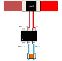
Even a conceptually simple function such as inserting a series resistor and reading the voltage across it requires attention to detail. The TSC1801 datasheet points out the often repeated but easily overlooked reality (Fig. 3):
“Particular attention must be paid to the layout of the PCB tracks connected to the amplifier, load, and power supply. The power and ground traces are critical as they must provide adequate energy and grounding for all circuits. The best practice is to use short and wide PCB traces to minimize voltage drops and parasitic inductance. In addition, to minimize parasitic impedance over the entire surface, a multi-via technique that connects the bottom and top layer ground planes together in many locations is often used. The copper traces that connect the output pins to the load and supply pins should be as wide as possible to minimize trace resistance.”
Reference
STMicroelectronics, “Low-side current sensing”
Articles related to current sensing

About the Author

Bill Schweber
Contributing Editor
Bill Schweber is an electronics engineer who has written three textbooks on electronic communications systems, as well as hundreds of technical articles, opinion columns, and product features. In past roles, he worked as a technical website manager for multiple topic-specific sites for EE Times, as well as both the Executive Editor and Analog Editor at EDN.
At Analog Devices Inc., Bill was in marketing communications (public relations). As a result, he has been on both sides of the technical PR function, presenting company products, stories, and messages to the media and also as the recipient of these.
Prior to the MarCom role at Analog, Bill was associate editor of their respected technical journal and worked in their product marketing and applications engineering groups. Before those roles, he was at Instron Corp., doing hands-on analog- and power-circuit design and systems integration for materials-testing machine controls.
Bill has an MSEE (Univ. of Mass) and BSEE (Columbia Univ.), is a Registered Professional Engineer, and holds an Advanced Class amateur radio license. He has also planned, written, and presented online courses on a variety of engineering topics, including MOSFET basics, ADC selection, and driving LEDs.
Comment About the Article
To join the conversation, and become an exclusive member of Electronic Design, create an account today!

Leaders relevant to this article: