Low-Current, Noise Gain Blocks Handle Up to 29.5 GHz

With their sights set on applications such as 5G mmWave infrastructure, Ka-band satellite communication links, and microwave backhaul, the 17- to 23-GHz CMX90B701 and pin-compatible 23- to 29.5-GHz CMX90B702 gain blocks in the SµRF product family from CML Microcircuits target interstage-amplification needs. Input and output ports are matched to 50 Ω, enabling these devices to be easily “dropped into” the RF signal chain with a minimal number of external components, plus they offer an optimal balance between low power consumption and performance (Fig. 1).
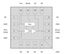
Based on gallium-arsenide (GaAs) pHEMT technology, these 3- × 3-mm VQFN-16 devices offer an optimal balance between output power, linearity, and noise. Key specifications include a typical P1dB output figure of +7.5 dBm, an IP3 output of +17.5 dBm (both at 20 GHz), small-signal gain of 17 dB, and noise figure of 4 dB. An active bias circuit helps maintain their performance over a wide temperature range (rated to 105°C operating temperature) and a supply voltage of 3 to 5 V. A package pin controls enable/standby mode.
Despite the apparent simplicity of role and associated circuit connections of these gain blocks, potential users will likely want to investigate many operating characteristics. Recognizing this reality, the 18-page datasheet includes over 60 graphs defining performance across multiple parameters and conditions, as well as additional tables.
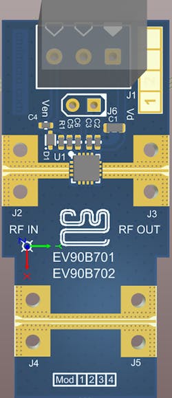
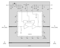
In addition, the datasheet features the 20- × 45-mm EV90B701 evaluation board (Fig. 2). It offers a full—albeit simple—schematic and bill of materials (BOM) (Fig. 3). The BOM shows that the evaluation circuit requires just six capacitors, one diode, one zero-ohm “dummy” resistor, and connectors.
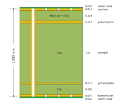
The datasheet also shows the multilayer stackup used for the evaluation board, which consists of a top layer of MT40 material (DK/εr = 3.53) on top of two layers of more common FR-4 (Fig. 4).
About the Author

Bill Schweber
Contributing Editor
Bill Schweber is an electronics engineer who has written three textbooks on electronic communications systems, as well as hundreds of technical articles, opinion columns, and product features. In past roles, he worked as a technical website manager for multiple topic-specific sites for EE Times, as well as both the Executive Editor and Analog Editor at EDN.
At Analog Devices Inc., Bill was in marketing communications (public relations). As a result, he has been on both sides of the technical PR function, presenting company products, stories, and messages to the media and also as the recipient of these.
Prior to the MarCom role at Analog, Bill was associate editor of their respected technical journal and worked in their product marketing and applications engineering groups. Before those roles, he was at Instron Corp., doing hands-on analog- and power-circuit design and systems integration for materials-testing machine controls.
Bill has an MSEE (Univ. of Mass) and BSEE (Columbia Univ.), is a Registered Professional Engineer, and holds an Advanced Class amateur radio license. He has also planned, written, and presented online courses on a variety of engineering topics, including MOSFET basics, ADC selection, and driving LEDs.
Comment About the Article
To join the conversation, and become an exclusive member of Electronic Design, create an account today!

Leaders relevant to this article: