Solid-State LiDAR May Overtake Today’s Electromechanical Approaches
What you'll learn:
- The limitations of rotating LiDAR systems and why a phased-array approach offers possible advantages.
- Why the phased-array approach has potential performance shortcomings due to element spacing.
- How MIT used advanced electromagnetic theory and modeling to devise a “workaround” for the spacing dilemma.
You’re no doubt familiar with the classic rotating radar antenna used for tracking aircraft, ships, and movements (Fig. 1). This antenna, which has been successfully and widely used for many decades, integrates numerous moving parts including slip rings for conveying power and signal between the stationary base and the moving top-side assembly.
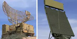
In many applications, however, these rotating radar antennas have been replaced by phased-array antennas that electronically steer the beam. Such beamforming offers advantages of no moving parts and the ability to dynamically control and change both the radar beamwidth and scan direction.
There is an optical parallel to RF-based radar: light detection and ranging (LiDAR). In operation, that’s analogous to early radar systems (the RADAR acronym for radio detection and ranging is no longer capitalized, and is now used as a lower-case word). LiDAR systems scan using a rotating mirror driven by a precise but complex mechanism.
The LiDAR challenge is further complicated by the fact that many of its installations are in mobile scenarios, such as autonomous vehicles of various types. Thus, they’re subject to shock, vibration, and other aggravations. For these reasons, a no-moving-part version using some sort of optical phased array would be very desirable.
LiDAR Sensors Based on Silicon Photonics
That’s what a team at the Massachusetts Institute of Technology (MIT) developed using an aray of silicon-photonics-based LiDAR sensors. This array can systematically scan an emitted light beam in multiple directions non-mechanically using an integrated optical phased array (OPA). By adjusting the phase of light routed to each antenna, the researchers can change the angle at which the light is emitted out of the array. In this way, they’re able to steer the beam and do so without moving parts.
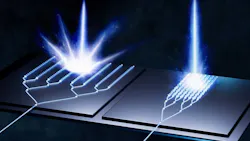
It seems like an obvious solution, so what’s been the obstacle? Not surprisingly, it’s a tradeoff scenario. If the multiple emitting sources (let’s call them antennas) are too close together, their outputs will couple with each other (called evanescent coupling) and the light they emit will get jumbled (Fig. 2).
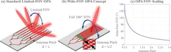
To avoid that, designers typically space the antennas farther apart, but this also has downsides. If the sources are spaced too far apart, the array will emit multiple copies of the light beam at different angles. Thus, the primary beam can only be a limited angle in either direction before it’s undiscernible from its neighboring copies. These beam copies, called grating lobes, could cause false positives by confusing the sensor (and they also waste power).
The MIT researchers solved this problem by designing a set of reduced-crosstalk antennas that can be placed close together without causing a significant coupling effect (Fig. 3).
In a standard OPA, all of the antennas have the same design, meaning the same arrangement of corrugations. These identical antennas couple very strongly when placed close together.
Antennas with Different Geometries
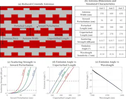
To address this fundamental roadblock, the MIT researchers designed a set of three antennas with different geometries, varying the width of each antenna and the size and arrangement of corrugations. With these varied geometries, each antenna has a different propagation coefficient, which determines how light travels down the antenna. Thus, each antenna doesn’t “see” the antenna next to it and won’t couple with its neighbor.
The design required that the antennas meet three objectives:
- Each antenna must emit the same amount of light.
- Each antenna must emit a beam at the same angle for the same wavelength of light.
- The emission angle must change uniformly across the array as it’s steered.
These are difficult, challenging, and somewhat contradictory requirements. The antennas need different geometries to reduce the crosstalk, but simultaneously they should have the same emission characteristics. While it’s possible to engineer this, it becomes extremely difficult because when antennas are designed with different geometries, they typically tend to behave differently.
The team approached the problem by doing an intense deep dive into fundamental electromagnetic-field theory expressing how radiative modes couple. They used that theory as a guide to design and simulate their antennas. They then fabricated the OPA with reduced-crosstalk antennas spaced significantly closer than they would be in a traditional OPA and experimentally tested the system (Fig. 4).
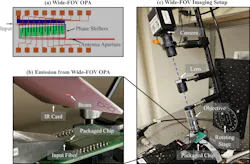
Their OPA reduced coupling to about 1% while generating a single, precise beam. They were able to demonstrate accurate beamsteering across a wide field of view without any grating lobes along with a wide field of view (FOV) (Fig. 5).
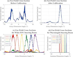
Note that this scheme provides a 180-degree FOV rather than the 360 degrees of an electromechanical spinning LIDAR, but there may be ways to work around this with multiple arrays. Full details, including some of the intense EM-field analysis, is in their paper “Reduced-crosstalk antennas for grating-lobe-free and wide-field-of-view integrated optical phased arrays” published in Nature Communications.
>>Check out this TechXchange for similarly themed articles and videos

About the Author

Bill Schweber
Contributing Editor
Bill Schweber is an electronics engineer who has written three textbooks on electronic communications systems, as well as hundreds of technical articles, opinion columns, and product features. In past roles, he worked as a technical website manager for multiple topic-specific sites for EE Times, as well as both the Executive Editor and Analog Editor at EDN.
At Analog Devices Inc., Bill was in marketing communications (public relations). As a result, he has been on both sides of the technical PR function, presenting company products, stories, and messages to the media and also as the recipient of these.
Prior to the MarCom role at Analog, Bill was associate editor of their respected technical journal and worked in their product marketing and applications engineering groups. Before those roles, he was at Instron Corp., doing hands-on analog- and power-circuit design and systems integration for materials-testing machine controls.
Bill has an MSEE (Univ. of Mass) and BSEE (Columbia Univ.), is a Registered Professional Engineer, and holds an Advanced Class amateur radio license. He has also planned, written, and presented online courses on a variety of engineering topics, including MOSFET basics, ADC selection, and driving LEDs.
Comment About the Article
To join the conversation, and become an exclusive member of Electronic Design, create an account today!

Leaders relevant to this article: