Simple Pulse-Width Modulator Controls Heater In Electric Jacket

A friend bought an electric jacket to wear on his motorcycle. But it was on all the time when it was plugged in, which made him sweaty at certain temperature ranges. He was looking for a way to control the heater inside the jacket.
He tried the simple route and put a potentiometer in-line with the jacket. But he found that it got so hot, it began to smoke and melted his gloves. (The heater circuit draws upwards of 5 to 10 A.) To solve the problem, I designed and built the circuit in Figure 1.
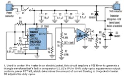
JP1 and JP2 connect in-line between the suit and the motorcycle, enabling the unit to control the current entering the suit. Capacitors C1 and C2 are power-supply bypass capacitors to help isolate the 555 timer (U1) from noise on the power line. Likewise, C3 and C4 bypass op-amp U2.
The 555 is set up to run as an astable multivibrator. Resistor R1 and capacitor C5 set the resonant frequency to approximately 1.5 kHz. Resistor R3 terminates the 555's output.
The 555 uses the external components to develop an approximate triangle wave to set and reset an internal Schottky switch. When in one state, C5 is allowed to charge through R1 until the logic switches. At this point, it will discharge through R2 until the first state is achieved, cycling endlessly until system power is cycled. The on/off points for switching are near 1/3 and 2/3 VCC (in this case, about 4 and 8 V).
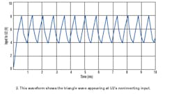
The upshot of this operation for use as a pulse-width-modulator circuit is an approximate triangle wave (Fig. 2). The triangle wave is employed as the input to op-amp U2.
U2 is a 741 op amp that's used as a comparator. The noninverting input is fed the triangle wave from the 555. The inverting input is fed a dc voltage determined by resistors R4 and R7 and potentiometer R5. By varying R5, the dc voltage on the inverting input ranges from just under 4 V to just over 8 V.
The resulting output of U2 is a square wave at the same frequency as the oscillations of U1, with a duty cycle ranging from 0% (off) to 100% (full on). The duty cycle is determined by the amount of time the triangle wave is greater than the dc control voltage. This output is fed to power FET M1.
M1 can be any power FET, but it must have a low on-resistance, preferably on the order of 0.01Ω. (A 0.01-Ω on-resistance could result in about 1/4-W power dissipation during full on.) R6 pulls down the input to M1. With the input pulled down, turning the system off (via switch S1) causes the system to break the return path of the suit's heater and shuts off the suit.
Diodes D1 and D2 dampen any flyback effects that may be generated by the inductance of the suit's heater coils. Granted, the inductance is small. But at these current levels, I want to make sure my friend doesn't get shocked.
About the Author
Comment About the Article
To join the conversation, and become an exclusive member of Electronic Design, create an account today!

Leaders relevant to this article: