Type-C Connectors Seize Multi-Interface Versatility
This file type includes high resolution graphics and schematics when applicable.
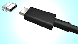
Is the VESA USB 3.1 Type-C connector (Fig. 1) the one connector that will rule them all? It may very well be the only connector on host devices like smartphones, tablets, and laptops in the future, with its ability to handle a range of interfaces beyond USB 3.1. It’s also reversible (see “USB 3.1 Type C Connector Is Reversible”) and can carry more power. Of course, with signals running at 10 Gb/s, the USB connection can be a challenge to test (see “Why Is the USB Type C Connector So Testy?”).
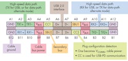
So, what’s behind this multilingual, “alternate mode” nature of the Type-C connection? To start with, the 24-pin connector (Fig. 2) has multiple communication links, including a USB 2.0 and high-speed serial interface that defaults to USB 3 (it runs independently of the USB 2.0 interface on different pins). In addition, a configuration interface actually controls power and the high-speed path, which is where the connector gets its multiprotocol support.
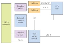
Essentially, the two devices at either end of the cable negotiate the interface to be used with the high-speed serial connections (Fig. 3). A crossbar switch redirects the high-speed Type-C connections to the appropriate redrivers connected to the host’s I/O hub. The External detection control tackles overall configuration (including determination of the host device, where appropriate) as well as USB power management. A USB 2.x device was limited to 500 mA or 2.5 W, while USB 3.1 handles up to 100 W.
For now, multichip solutions are the most likely to implement connections that support more than one interface. In the future, though, look for popular platforms to emerge with combinations like USB 3/DisplayPort. These will typically be found on host devices like smartphones, tablets, and laptops, but there are scenarios where alternate-mode operation makes sense. For example, a display device might support DisplayPort, USB 3, and even PCI Express. Consequently, the display could be driven by a host that had only of these interfaces. Devices that support more than two modes will likely be rare, given the added cost and complexity for multiple-interface support.
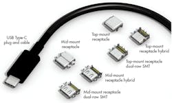
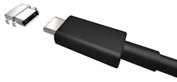
These small Type-C connections come in various forms to address a range of installations (Fig. 4). Note that the same connector is at both ends of the cable, compared to the typical USB cable with a different connector at each end. It’s built this way for two reasons. First, control, power, and data transfers can start at either end, and have different sources. For example, a device could be a slave but provide power. It allows for scenarios such as connecting a smartphone to a tablet. Second, the approach simplifies cable construction and cable use. There is no wrong way to plug it in.
The Type-C connection is just starting to make an impact on system design and consumer usage patterns. In the end, it may be the one connector that outlasts them all.
This file type includes high resolution graphics and schematics when applicable.
About the Author

William G. Wong
Senior Content Director - Electronic Design and Microwaves & RF
I am Editor of Electronic Design focusing on embedded, software, and systems. As Senior Content Director, I also manage Microwaves & RF and I work with a great team of editors to provide engineers, programmers, developers and technical managers with interesting and useful articles and videos on a regular basis. Check out our free newsletters to see the latest content.
You can send press releases for new products for possible coverage on the website. I am also interested in receiving contributed articles for publishing on our website. Use our template and send to me along with a signed release form.
Check out my blog, AltEmbedded on Electronic Design, as well as his latest articles on this site that are listed below.
You can visit my social media via these links:
- AltEmbedded on Electronic Design
- Bill Wong on Facebook
- @AltEmbedded on Twitter
- Bill Wong on LinkedIn
I earned a Bachelor of Electrical Engineering at the Georgia Institute of Technology and a Masters in Computer Science from Rutgers University. I still do a bit of programming using everything from C and C++ to Rust and Ada/SPARK. I do a bit of PHP programming for Drupal websites. I have posted a few Drupal modules.
I still get a hand on software and electronic hardware. Some of this can be found on our Kit Close-Up video series. You can also see me on many of our TechXchange Talk videos. I am interested in a range of projects from robotics to artificial intelligence.
Comment About the Article
To join the conversation, and become an exclusive member of Electronic Design, create an account today!

Leaders relevant to this article: