How to make triacs and LEDs get along
Energy-efficient lighting is in the headlines as we approach the date at which federally mandated efficiency levels for lights will make ordinary incandescent lighting obsolete. Incandescent lights typically provide less than 20 Lumens of light per Watt of power consumed. Compact fluorescent (CFL) bulbs have been the energy-efficient replacement lamp of choice because of their relatively low costs. However, the light-emitting diode (LED) light bulb is the technology to watch. It is likely that over the next few years LED-based bulbs that are both dimmable and of high quality will become available at affordable prices and will eventually replace not just incandescent bulbs but CFLs as well.
It it useful to review the main factors that make CFLs problematic light sources. They each contain a gram or two of toxic mercury, which poses a problem if the bulb breaks or is not recycled properly. CFLs also are notorious for emitting light that renders colors poorly. And it can take several minutes for the bulb to reach a thermal steady state — light output is greatly reduced when the lamp is cold.
CFL lamps also must be driven by a magnetic or electronic ballast, and as such are not normally dimmable from the standard wall dimmers already installed in many millions of homes. In fact the usual result of putting a CFL on a conventional dimmer is severe flickering and in some cases damage to the CFL or dimmer electronics. The flickering arises from the phase cut method of operation employed by dimmers based on triacs when connected to capacitive loads typical of the electronic converters in CFL ballasts.
To briefly review the source of this problem, a triac switch in a dimmer activates with a pulse applied to its gate terminal which happens at a point in the ac cycle determined by the dimmer level. The triac then switches on and conducts until its current drops below a threshold known as the holding current. If connected to a capacitive load, the current can drop below the holding current before the end of the cycle causing it to fire and switch off several times during a cycle. This problem is aggravated further by the ringing oscillations created by the capacitance and inductance of EMI filter components reacting to a large voltage transition when the triac switches on.
There have been LED-based bulb replacement products in various forms for the last few years, but they have tended to be prohibitively expensive. Moreover, they often could not put out enough light for general use and could not be dimmed. But a new generation of products with greatly improved electronic drive circuitry has overcome these limitations. The U.S. Dept. of Energy (DOE) and the Environmental Protection Agency (EPA) have led an effort to define performance requirements for LED replacement lamps. Their goal is to justify the cost of replacing other light sources by offering a quantifiable environmental advantage through use of LEDs. A product which complies with the standard will qualify for the Energy Star rating.
Energy Star requirements now cover luminous efficacy, power factor and dimmability of LED-based bulbs. The integrated electronic drivers in these devices generally use non-isolated switching current regulators combined with additional circuitry that is often incorporated into smart driver ICs. Specialized circuitry enables dimming from a standard triac-based wall dimmer. Energy Star also specifies a minimum 0.7 power factor for LED bulbs that are over 5 W.
LED based replacement light bulbs have been around for a few years but many early products didn't perform well, partly because their manufacturers cut corners to compete with relatively inexpensive CFLs mass produced in Asia.
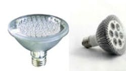
Today consumers can find a variety of LED light bulb products ranging from small candle lamp replacements with power rating of only 2 W to PAR30-type replacements which range from 3.5W to 9 W.
LED replacement bulbs can be broadly separated into two categories. The first is passively driven, containing only basic circuitry for limiting the LED current: typically a bridge rectifier and resistor/capacitor network. The second is actively driven and contains an LED driver circuit: typically a compact switching power supply that regulates LED current. Passive LED drivers can provide only limited amounts of current (at higher currents the required circuitry becomes impractically bulky). They also compensate for variations in the LED forward voltage drop caused by temperature and tolerances. Typically, passive drivers work with standard white LEDs running at perhaps 20 mA, rather than high-brightness LEDs, which operate at a much higher current.
Despite several limitations, passively driven systems can produce reliable and inexpensive LED replacements that can provide useful amounts of light. Potential problems include a low conversion efficiency and the need for capacitors that can be prohibitively large.
As an example, the accompanying passive circuit operates at 5 W driving about 100 LEDs in series. It has a power factor of 0.6 and cannot be dimmed by a standard dimmer. Thus it would not qualify for Energy Star rating.
In contrast, actively driven LED light bulbs almost always use switching LED drivers based on the Buck regulator, a basic and widely used switching power supply circuit topology. This provides conversion efficiency of 85% or better and reasonably accurate regulation of the LED current over variations in ac line voltage. It also keeps the LED forward voltage drop relatively constant despite temperature and tolerance changes.
The Buck regulator works well as an LED driver because the output voltage required to supply the LEDs is always lower than the ac line input voltage. Live parts of the circuit can be double insulated from the outside casing so there is no need for isolation transformers or other means of keeping circuitry away from line voltages. A simple Buck LED driver switching at 100 kHz or higher can utilize a small inductor combined with a single switching MOSFET, a diode and a simple control IC. With additional circuitry it is also possible to include power factor correction and compatibility with standard triac based dimmers.
The accompanying circuit shows a basic off-line LED driver circuit with no dimming circuitry or power factor correction. The control IC (IC1) supplies a PWM gate drive signal to the switching MOSFET (MBUCK). A shunt resistor (RCS) senses the LED current and switches off the MOSFET when it reaches a threshold voltage set by IC1. The current then drops until it reaches a lower threshold, at which point the MOSFET switches on again.
This free running hysteretic mode of operation regulates the average LED current. Frequency and duty cycle adjust to whatever is determined by the load and inductance of LBUCK. The IC contains an internal high voltage regulator, allowing it to operate from the rectified dc bus. It takes few components to realize this circuit and those involved are small enough to let the whole circuit sit in the base of a lamp.
It takes additional components to make the LED driver dimmable and improve the power factor. This inevitably adds to the size and cost, but there are ways to minimize these penalties. To increase the power factor, the dc bus capacitor can be reduced so a large component of ripple will be present at twice the line frequency. This will enable current to be drawn from the line for a larger portion of the ac cycle. This, in turn, may be enough to boost the power factor to above the 0.7 limit.
An additional MOSFET (MHOLD) has been incorporated to form a bleeder circuit controlled by the IC. This acts as a current sink drawing approximately 20 mA of current from the ac line for the whole cycle. This level of current prevents the triac in the dimmer, once it has fired, from switching off again before the zero crossing of the ac line voltage. There is some unavoidable power loss in RHOLD which reduces the efficiency a little. To reduce the ringing effect, the filter components have been moved to the dc side of the circuit.
The IC dims the LED by first detecting the triac firing angle and then translating information into a PWM signal. This signal is used for dimming the output in burst mode at a frequency in the order of 1 kHz.
Resources
International Rectifier, www.irf.com
Want More?
Focus on this code image using your smartphone and free software from neoreader.com and you will be connected to related content on eetweb.com
http://eetweb.com/lighting/make-led-fixtures-energy-efficient-201011/
About the Author
Peter B. Green
(LED Group)
Comment About the Article
To join the conversation, and become an exclusive member of Electronic Design, create an account today!

Leaders relevant to this article: