CAD to the rescue for fluorescent dimmer design
Peruse a few online help forums about lighting and you'll quickly conclude that it's tough to dim fluorescent bulb loads. The dimming of fluorescent lamps can indeed be difficult because of their electrical behavior and specifications. Fortunately it has become easier to design dimmable electronic ballasts for fluorescent lamps thanks to the advent of software that provides design assistance for such tasks.
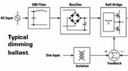
To see how such software can be helpful, the place to start is with a review of fluorescent dimming techniques. An electronic ballast that supports dimming typically includes an EMI filter for blocking ballast-generated noise; a rectifier and smoothing capacitor for converting the ac line input into a dc bus voltage; a half-bridge (and control IC) for producing a high-frequency square-wave voltage; a resonant tank circuit for preheating, igniting and dimming the fluorescent lamp; a current-sensing circuit to measure the lamp current; a feedback circuit to regulate the lamp current to a desired level; and a user-defined dimming input (typically galvanically isolated) to set the dimming level. The dimmer typically uses a closed-loop system to regulate the lamp current because fluorescent lamps have non-linear electrical qualities.
One program available to help speed up the design of dimming ballasts is the BDA (Ballast Design Assistant) from International Rectifier. This free program runs on an ordinary PC. BDA severs as an example of what such software can do. The program first lets the designer select the target IC, select the input circuit configuration, select the lamp type, and then select the lamp circuit configuration. The example depicted in accompanying screen shots uses the IRS2530D dimming IC, a 185 to 265-Vac full-bridge rectifier input configuration, a TC-DEL 26-W lamp, and a single lamp voltage-mode heating configuration.
If the designer is satisfied with this circuit, the program can generate a bill of materials and inductor specifications. But an advanced option can let the designer see more details of the design if need be. The advanced screen lets the designer see, edit and fine-tune the ballast and lamp input specifications, calculate the resonant tank components, and graphically see the circuit operating points. The resulting analysis gives a better understanding and feeling of how the circuit will work and, in particular, how the resonant tank will behave during the different modes of the lamp.
A “calculate” option uses ballast and lamp input data to determine the resonant tank component values (L and C) together with the various' operating frequencies that correspond to each lamp mode. The software also generates a Bode plot to show the operating points graphically. In the accompanying example, the L and C values are calculated as 2.8 mH and 6.8 nF respectively. The circuit starts up at 76.7 kHz and then sweeps down toward the resonant frequency (36.5 kHz) of the under-damped resonant curve. As the frequency sweeps down, the voltage across the lamp rises as the gain of the under-damped resonant curve increases.
When the frequency reaches the calculated ignition frequency (40.6 kHz), the voltage across the lamp will be approximately 750 Vpeak and the lamp will ignite. The resonant tank will become damped because of the lamp resistance present in the circuit. The IRS2530D Dimming Control IC will then close the feedback loop and adjust the frequency to somewhere between the 100% frequency (30.7 kHz) and the 10% frequency (50.7 kHz), depending on the desired dimming level. The resonant tank will become more or less damped as the lamp resistance rises or falls during dimming. The key to good ballast design is to know where the operating points are at all times.
When the input and output circuit parameters are acceptable, the designer can select the “inductor calculator” to generate a specification for the resonant inductor that includes core type, core size, air gap, number of turns, and wire gauge. From the advanced screen the designer can also select the “component calculator” to load in the circuit output parameter data from the advanced screen and calculate the various programming resistors and capacitors around the IRS2530D.
The BDA software also includes a “time domain” waveform viewer accessible from the component calculator screen. This feature employs a numerical differential equation solver to figure voltage and current waveforms of the half-bridge and resonant tank output circuits. In addition to checking the operating points generated from the advanced screen, the designer can also check the simulated time domain switching waveforms to make sure the circuit will work as expected before building the actual circuit on the bench.
The waveforms include the half-bridge switching voltage; the resonant inductor and capacitor currents; and the lamp voltage and current during frequency sweep, ignition and running lamp modes. A review of these waveforms for the example at hand shows the resonant inductor current rises as the frequency drops toward the resonant frequency of the under-damped resonant tank until it reaches a peak when the lamp ignites. After the lamp ignites, the current then falls to a lower level because of the damping from the lamp resistance.
The time domain viewer also lets the designer zoom in at any point in time along the x-axis to see the waveforms in more detail. During 100% dimming, the half-bridge voltage is a square-wave operating at the 100% frequency (30.7 kHz) with a 50% duty cycle and switching between ground and the dc bus voltage. The resonant tank waveforms all show their respective ac quasi-sinusoidal resonant behaviors.
When the designer finally asks the program to design the ballast, the program will generate the schematics, bill of materials and inductor specifications. The resulting documents provide the information needed to build a prototype on the bench, turn on the lamp, and evaluate the circuit performance.
HD-Resources
To download the free BDA software, visit International Rectifier, www.irf.com
Comment About the Article
To join the conversation, and become an exclusive member of Electronic Design, create an account today!

Leaders relevant to this article: