Engineering LED Drivers for Incandescent Bulb Replacement is a BOM Challenge
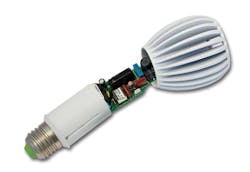
LED-based bulbs that replace their incandescent counterparts require a significant amount of engineering (Fig. 1). In the 60 W range the LED driver board can take up about 15% of the overall cost of the bulb. Consumer price pressure on the LED driver IC manufacturer has forced its designers to work with one hand on a calculator and the other hand on an oscilloscope.
For example, designers have a choice between using a power MOSFET or bipolar junction transistor (BJT) to power the LEDs. The MOSFET may cost $.12 where the BJT is only $.07. Therefore, the BJT wins the fight for a lower bill of materials (BOM).
Price pressure also involves the use of power factor correction (PFC). Worldwide regulations mandate PFC and minimum power line harmonics. These regulations vary by country and by application. The traditional PFC circuit requires a two-stage circuit, which increases the BOM. Therefore, some manufacturers have opted for a less costly single-stage design. This simpler single-stage technique lowers the cost, but it can impact the ripple current through the LED that causes objectionable flicker. A single-stage design has an inherent trade-off between the PF and output ripple. It is possible for single-stage PFCs to provide an adequate power factor with relatively low output ripple, minimizing both heat and flicker, with little impact on overall cost or size.
LED bulb operating temperature is another design-cost consideration, particularly for residential use where the bulb may be in a location with little or no cooling. This requires some form of over-temperature protection (OTP) to protect internal bulb circuits.
Fig. 1. Cutaway view of a typical LED replacement bulb.
Isolated and non-isolated LED drivers may be employed. Isolated types require a transformer, whereas the non-isolated version eliminates that cost. However, the non-isolated driver incurs other costs because it requires heavier insulation and a more costly mechanical enclosure. This is another design-cost tradeoff.
Driver Design
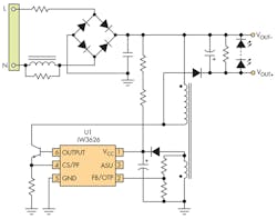
The iW3626 from iWatt takes into account these design-cost tradeoffs, a non-dimmable LED driver for incandescent lamp replacement (Fig. 2).
Fig. 2. iW3626 non-dimmable LED driver provides capability for incandescent lamp replacement.
It is a high performance, power factor corrected, AC/DC power controller for LED luminaires (Fig. 3). The IC uses digital control technology in a PWM flyback power supply to achieve relatively high power factor while minimizing LED current ripple. It operates in quasi-resonant mode to provide high efficiency along with a number of key built-in protection features that minimize the external component count. This simplifies EMI design and lowers the BOM.
Fig. 3. Application circuit for iW3626 employs transformer that enables non-isolated design.
As shown in Fig. 3, its features include:
- All-in-one non-dimmable low-cost off-line LED driver
- Supports universal input voltage range (90V – 277V) up to 10W
- Supports isolated or non-isolated LED driver
- Isolated design without opto-coupler
- Supports wide range of LEDs with tight current regulation
- Helps reduce light flicker
- Active start-up scheme enables fastest possible start-up
- No audible noise over entire operating range
The iW3626 removes the need for a secondary feedback circuit while achieving excellent LED current regulation over line and load variation. It also eliminates the need for loop compensation components while maintaining stability under all operating conditions.
iWatt’s proprietary technology maximizes the iW3626 performance in a small SOT-23 package. The iW3626 offers two multi-function pins allowing users to configure PFC and OTP threshold as required with no cost and size impact, thereby providing design flexibility.
Configurable PFC is achieved using iWatt’s patent-pending hybrid control method that adaptively switches between constant current and TON control modes within an AC cycle. TON is the duration of the switch in the ON position (the width of a PWM cycle). This hybrid control method shapes the TON width, effectively setting the amount of time allocated for the constant current control versus the TON control. The IC’s PFC circuit provides:
- Tight current regulation over line/load ranges (± 3%)
- Power factor adjustable from 0.7 to 0.9
- Low current ripple
- Cycle-by-cycle regulation
- Built-in compensation for AC line voltage variation
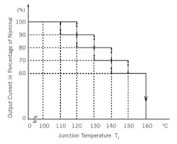
Fig. 4 shows how the iW3626 reacts to its junction temperature, which is an indication of the temperature inside the sealed LED bulb.
Fig. 4. The iW3626 over-temperature protection derating characteristics relationship between output current vs. junction temperature.
When junction temperature reaches a point set by the system designer, the iW3626 LED driver automatically reduces the current drive to the LED. This lowers the power dissipation and results in cooler overall operation. This reduces the risk of thermal runaway and ensures the temperature rating of the electrolytic capacitors in the system is not exceeded, thereby helping ensure predictable bulb operating life. Additional built-in protection features include LED open/short, input over-voltage, over-current, and current-sense resistor short protections.
Table 1 lists the characteristics of three of iWatt’s drivers for LED bulb replacement.
About the Author

Sam Davis
Sam Davis was the editor-in-chief of Power Electronics Technology magazine and website that is now part of Electronic Design. He has 18 years experience in electronic engineering design and management, six years in public relations and 25 years as a trade press editor. He holds a BSEE from Case-Western Reserve University, and did graduate work at the same school and UCLA. Sam was the editor for PCIM, the predecessor to Power Electronics Technology, from 1984 to 2004. His engineering experience includes circuit and system design for Litton Systems, Bunker-Ramo, Rocketdyne, and Clevite Corporation.. Design tasks included analog circuits, display systems, power supplies, underwater ordnance systems, and test systems. He also served as a program manager for a Litton Systems Navy program.
Sam is the author of Computer Data Displays, a book published by Prentice-Hall in the U.S. and Japan in 1969. He is also a recipient of the Jesse Neal Award for trade press editorial excellence, and has one patent for naval ship construction that simplifies electronic system integration.
You can also check out his Power Electronics blog.


