Intelligent LED Driver Employs Ledotron Digital Dimming
The first device from the smarteXite family, the iW6401, supports multiple dimming interfaces, including digital dimming via the new Ledotron™ digital dimming protocol and toggle-switch based dimming. All dimming-curves can be memory-configured to enable a highly optimized end-user lighting experience. The integrated digital loadline transmission (DLT) receiver in the iW6401 supports the Ledotron IEC 62756-1 dimming protocol, making it the world’s first single-chip plug-and-play Ledotron solution.
Ledotron was a cooperative development between European companies Insta and OSRAM. Ledotron control units and lamps can already be obtained in specialized trade. In the future, it will even bring an additional application benefit by adding options for controlling color, color temperature and lamp groups.
Related Articles
- Dimming LED Lamps: It All About the BOM vs. Lifetime and More
- Dimmable LEDs Have A Bright Future
- Dimming Techniques for Switched-Mode LED Drivers
- How to Add Analog Dimming to Virtually Any LED Driver
Why a new dimming process?
Introduction of the European Eco Design Guideline [1] in 2005 and 2009 completely changed dimming control techniques. The less efficient incandescent lamps were gradually banned from the market and replaced with the more efficient compact fluorescent lamps (CFLi) and LED lamps. The CFL and LED lamps could not employ incandescent lamp dimming approaches that caused problems, such as:
· Flickering during setting and in operation
· No lamp start in lowest dimming position
· Unsteady dimming course
· High minimum brightness
· Small dimming range
· Noise development
· No reliable compliance to EMC requirements on limits for harmonic current emissions [2]
· No reliable compliance to EMC requirements on radio disturbances [3]
Insta and OSRAM decided not to optimize existing analog dimming technologies, because the dimming processes and above all the ballasts in the new lamps are not subject to any standard and develop rapidly and in many ways.
Therefore Insta and OSRAM developed the Ledotron digital dimming and control process with the aim of achieving an international standardization that granted interested companies license-free access to this problem-solving technology.
The following Ledotron system characteristics were defined and realized:
· For control unit and lamps, the existing wiring structure of two-wire-dimmers in flush-mounted boxes is sufficient, which makes renovation of existing buildings easy.
· Simple installation process, which enables the end-user to exchange lamps on his own.
· Compliance with highest quality standards in operation and dimming to achieve customer satisfaction.
· Undisturbed co-existence of several Ledotron circuits at one phase.
· Undisturbed co-existence with other digital services (Powerline etc.).
· Full compliance with all relevant standards.
· Safe conditions at any time, also if unsuitable dimmer-lamp combinations have been used by mistake.
· Additional benefit: option of controlling color, color temperature and grouping of suitable LED lamps and luminaires!
Ledotron Data Transmission
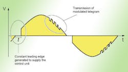
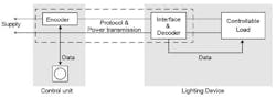
Ledotron operation let the mains sinusoid pass nearly fully to the lamp – independent of the desired brightness value of the lamp. (Only a small constant leading-edge cut provides that the control unit is able to power itself). The control unit contains an encoder that modulates information of the desired brightness and/or color information as digital telegram on the mains sinusoid. A decoder in the ballast of the lamp evaluates the telegram on the mains sinusoid and transmits the information to the power electronics of the lamp, which then operates the lamp with the desired values. Fig. 1 shows the simplified circuit.
This two-wire-technique control unit has no neutral terminal and therefore must supply itself by a low current via the lamp load. To this effect it generates a low constant leading-edge cut. The digital telegram is coupled to the falling slope of the mains sinusoid and stretches over several half-waves. The resulting signal run between control unit and lamp is shown in Fig. 2.
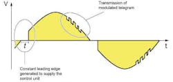
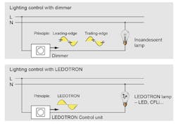
Fig. 3 compares dimming control for an incandescent and Ledotron-based system.
If, by mistake, a non-Ledotron-lamp is installed in a Ledotron-controlled luminaire, you will be able to switch it on and off without a problem, for the control unit passes on nearly full mains voltage. Dimming, however, is not possible, for the lamp cannot evaluate the telegrams.
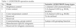
In Ledotron technology, different operation modes are defined that enable control unit and lamp to interpret the transmitted value in different ways. Primarily, there is a possibility to be able to interpret the transmitted values as brightness value, as color temperature value or as color value for red, green or blue content on lamp side. Therefore, the telegram contains three additional bits, defining an operation mode for control unit and lamp. Three bits can define up to eight operation modes. By cascading the telegram structure the theoretical number of possible operation modes can be extended. Table 1 defines the Ledotron operating modes.
In case control unit and lamp do not have exactly the same operation modes, both components will automatically set to the possible common operation modes.
Examples:
· A control unit with only one rotary button for brightness is combined with an RGB LED lamp.
Result: The RGB lamp can be operated in white light and can be dimmed.
· A control unit with RGB option is combined with a monochrome LED-lamp.
Result: the lamp with its monochrome light can be dimmed without problems, but of course the color cannot be changed.
Control Of Lamp Groups
For the typical application, in which one control unit controls one or several lamps, it was intentionally avoided to implement an addressing process. On the other hand it is of course interesting to be able to control several lamps in one control circuit independent of one another. To reach both targets at the same time, in the Ledotron telegram two-bit code is the address for lamp groups. If the group address is not used, for instance because the addresses of control unit and lamp are not assigned, address “0” is used automatically, to which all connected lamps react in the same way. If, however, an address assignment is supported by control unit and lamp, the lamps connected at one circuit can also be operated in three individually controlled lamp groups, as shown in Table 2.
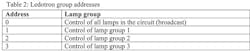
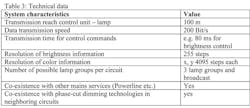
Table 3 lists additional Ledotron technical data.
International Standardization
The process to standardize DLT internationally is under way and corresponding activities are up and running in the relevant standardization committees.
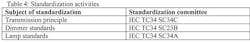
During these activities a CDV "Committee Draft for Voting" on the transmission principle with the standard description IEC 62756-1 has been filed with the IEC[4]. A successful standardization of DLT can be expected in 2014.
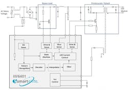
Fig. 4 shows s typical application diagram for Ledotron LED driver using iW6401. Using the iW6401 digital LED Control IC the implementation of a Ledotron enabled Lamp is easy and straightforward. The Bypass Load is controlled automatically according to the IEC Spec. No other additional components are needed in order to dim the lamp in the fully range w/o using decoded DLT dim data.
Benefit of LEDOTRON
Using Ledotron brings different benefits for the target groups, the most important being listed in Table 5.

References:
1. The European ban on incandescent lamps is defined in the eco design guideline
EuP 2005/32/EG, replaced by ErP 2009/125/EG
2. EN 61000-3-2: Electromagnetic compatibility (EMC) – Part 3-2: Limits – Limits for harmonic current emissions (equipment input current ≤ 16 A per phase)
3. EN 55015: Limits and methods of measurement of radio disturbance characteristics of
electrical lighting and similar equipment
4. IEC 34C/1027/CD:2012: Project IEC 62756-1 Ed. 1.0: Digital load side transmission lighting control - Part 1: Basic requirements
About the Author

Sam Davis
Sam Davis was the editor-in-chief of Power Electronics Technology magazine and website that is now part of Electronic Design. He has 18 years experience in electronic engineering design and management, six years in public relations and 25 years as a trade press editor. He holds a BSEE from Case-Western Reserve University, and did graduate work at the same school and UCLA. Sam was the editor for PCIM, the predecessor to Power Electronics Technology, from 1984 to 2004. His engineering experience includes circuit and system design for Litton Systems, Bunker-Ramo, Rocketdyne, and Clevite Corporation.. Design tasks included analog circuits, display systems, power supplies, underwater ordnance systems, and test systems. He also served as a program manager for a Litton Systems Navy program.
Sam is the author of Computer Data Displays, a book published by Prentice-Hall in the U.S. and Japan in 1969. He is also a recipient of the Jesse Neal Award for trade press editorial excellence, and has one patent for naval ship construction that simplifies electronic system integration.
You can also check out his Power Electronics blog.
Comment About the Article
To join the conversation, and become an exclusive member of Electronic Design, create an account today!

Leaders relevant to this article: