Proper Cooling Of LED Arrays and Power Converters Improves Performance, Reliability
Historically, dc-dc converters rated less than 25 W have been treated like most other pc board mounted components because they are typically rated for a given amount of power up to a certain ambient temperature. Converters classified as “high density,” however, are more closely associated with power levels above 25 W and range up to a few hundred watts. These high-density converters, unlike their lower power predecessors, are specified like power semiconductors and are rated in terms of their maximum allowable baseplate temperature, regardless of the ambient.
With LED lamps and fixtures, the heat removal challenges are more complex because of the required form factors. That means even at power levels as low as 7-10 watts, these designs need more attention so that LED chips do not overheat.
From a thermal management standpoint, a high-density dc-dc converter, like virtually all power supplies, can deliver substantial power, but only if excessive heat is removed by transferring internal heat through a number of materials to a surface exposed to surrounding air. Heat from that outer surface is then transferred to the surrounding air in proportion to the air turbulence immediately adjacent to that surface, whether that “turbulence” results in the form of fast-moving air (active cooling) or very tiny air “eddy currents” in a passively cooled system.
The reference to “outer surface” needs a further comment because no mention was made of a “metal” surface. The reason for this is that in a perfect situation all of the internal heat would originate from every cubic millimeter within the module and would be evenly distributed to all parts of the outer surface. Whether the outer surface is plastic or metal makes no difference as long as there is no effort to attach one of the hot surfaces to a heat sink; that is, as long as there is only (surface-to-air) convection cooling.
In a real world power module or light fixture, specific components (which can be either traditional power semiconductor or power LEDs) are the principal heat generators. The area adjacent to these components is usually hotter than other areas. An outer metal case or plate spreads the heat and reduces point-to-point temperature variations. With a high-density converter having a metal baseplate, the thermal conductivity of the plate material is an indispensable link to a cooling technique, which is better than simple surrounding air.
The baseplate has two functions: to spread the heat generated by small-surface-area power semiconductors and to conduct that heat to a cooler place. For the remainder of this discussion, the concentration will be on heat removal from the power semiconductors within the converters (or light fixtures) because they usually represent over 85% of the internally generated heat.
The process which final surface-to-air heat makes transfer is what determines the ultimate ability of a converter to deliver its maximum possible power. The barrier to perfect heat transfer is defined as “thermal resistance,” that is, the lower the thermal resistance, the better the heat transfers. Stated another way, the higher the thermal conductivity, the better.
However, it has become the convention in addressing power semiconductor and power supply thermal management to talk in terms of “thermal resistance” instead of thermal “conductivity.”
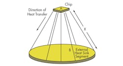
In practice, internal heat is never perfectly distributed and there are hot spots. Fig. 1 shows how heat from a point source, such as the chip within a MOSFT or power rectifier package reaches its destination. Heat travels outward in a conical path that is rarely a perfect cone because of the physical configuration of heat generators. Fig. 2 depicts the same process in a way that reflects the typical arrangement for heat removal from the power semiconductor in a dc-dc converter.
In an LED light fixture there is typically another set of thermal barriers between the chip tab or substrate and the heat sink. It is usually in the form of a metal-core PC board and related thermal interface material.
The ability of heat to get from one place (such as the chip) to another (the surrounding air) is determined by:
- The distance (thickness)
- The area (a large glass window transfers or loses heat faster than a small windoww.
- Thermal resistance of the various materials and interfaces through which the heat must pass.
Often not appreciated is the fact that a material of given thermal resistance has a more adverse effect the closer it gets to the point source of heat. Conversely, the actual thermal resistance of a given thickness of material becomes less important the more it is at the wide end of the het travel cone. This means that an infinite amount of heat sinking and airflow cannot keep the chip cool if the chip-to-case and case-to-heat sink surfaces have excessive thermal resistance. In some applications, the simple change to a chip of larger area and correspondingly lower junction-to-case thermal resistance could have more effect than an exotic fan and heat sink system.
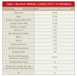
Table 1 compares a number of materials that often play a role in thermal management. It may be surprising that all epoxies, plastics and silicones fall into a narrow band from 10 to 30. There are no units for thermal resistance. The figures are normalized, using air as 1.0. Thermal resistance, unlike electrical resistance has a few conditions attached to it. It is influenced by the thickness and area of material, so Table 1 shows the relative difference in thermal resistance for different materials to be employed in an identical physical configuration.
Also, there is no such thing as a “thermally conductive” epoxy unless it is filled with a material higher up on the scale, such as aluminum oxide. One epoxy might be relatively more thermally conductive than another, but the thickness and area can often outweigh the actual material type.
Cooling Methods
A converter’s heat transfer can be enhanced by using one or more of the following techniques to lower the thermal resistance, i.e., the thermal conductivity from the internal converter heat sources to the outer air:
1. Use a large metal enclosure to expose more of the heated metal surface to the air, essentially enlarging the conical heat pipe diameter at the open end of the thermal cone. This option is not really available in a high-density converter because by definition, the high-density module footprint is probably small.
2. Blow air across the baseplate or metal surfaces of the case. The additional air turbulence at the metal surface speeds up the heat removal process by enlarging the cone’s large-end diameter. With converters, the degree of cooling for specific air speeds and area for the metal surface has been characterized. Typically, an air speed of 200 linear feet per minute (lfm), readily achieved with standard fans, is desired across the heat surface or heat sink fins in order to achieve substantial cooling. Air speeds much above 400-500 lfm are usually difficult to achieve in constricted areas and at the same time become marginally effective in removing much more heat.
3. Attach the case to a larger metal surface (spreading the heat) to expose more surface area to the surrounding air (similar to item 1). Often, this is not feasible unless there is a large aluminum chassis to which the unit can be attached.
4. Attach the baseplate to a finned heat sink across which air is blown. In the presence of air flow, the extra surface of the fins just like additional external unfinned metal surface area, as in item 3, but confines the extra within a more compact volume. It is important to understand that fins do not have much effect unless there is airflow in the direction of the fins. Cooling with finned heat sinks is generally the most effective practical cooling scheme for converters. For a given air flow, one inch-high fins can double the cooling effect over a baseplate without fins.
Fin spacing, fin height, air speed and air direction all contribute to the final effectiveness. A common mistake by designers is to dwell on the cubic-feet-per-minute (cfm) rating of fans when making assumptions about system cooling. The cfm of the fan tells us about the volume of air that is to pass immediately over the surface of the hot metal surface. It is the speed in linear feet per minute that is important.
A small fan, in a creative configuration with a finned heat sink, can dramatically outperform a large fan with a poorly thought-out fin arrangement. In the same way a small battery-operated hand-held fan six inches from ones face can cool far better than a giant fan 50 feet away.
An infinite number of possible schemes can be conceptualized, but there are a number of basic finned heat sink configurations, which, if used conservatively, will ensure proper cooling.
In cooling a converter, it is always understood that system assembly practices, unexpected changes in available air, or ambient temperatures may result in the converter being cooled a little less optimally than thought. Nevertheless, using the recommended finned heat sinks will prevent catastrophic failures under normal conditions.
Heat Sink Types
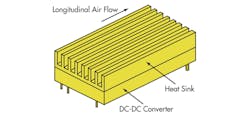
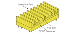
Heat sinks for the popular “half brick and “full brick” converter configurations are available from several vendors for what is called “longitudinal” air flow (along the same axis as the input-to-output power flow) or “lateral” air flow (across the unit). Fig. 3 shows a finned heat sink for longitudinal airflow and Fig. 4 shows a finned heat sink for lateral flow. That is, fins for lateral or longitudinal air flow are 90 degrees apart in terms of the flow axis. This means that fins must line up with airflow direction in order to be effective.
It is always important to have either thermal grease or a thin, thermally conductive, compliant material (thermal gap filler) between the heat sink and converter baseplate. Compliance allows the material to fill in surface irregularities. The greater the mismatch in flatness between the converter and the heat sink, the thicker the compliant material must be.
The most popular options are as follows.
1. Thermal grease is excellent for mating relatively flat surfaces and even some poorly matched surfaces (as long as there is a very thick layer of grease). Their disadvantage is that it is fairly messy and time consuming to get it right.
2. Thin (0.002-0.003-in.) aluminum foil with or without thin paraffin coating on both sides. The wax coating enhances the filling in of “micro” surface irregularities. Its disadvantage is that aluminum can sometimes develop “wrinkles” that adversely affect mating and heat transfer. Also, this approach means that there are two metal-to-compliant material interfaces. Every interface is, to a degree, an impediment to heat transfer.
3. Same as item 2, but the coating is on a thin layer of insulation typically a special (more thermally conductive) type of Kapton so that electrical isolation is also provided. Its disadvantage is that it is not as thermally effective as item 2.
4. Silicone-type elastomer materials are available from a number of suppliers. Typically used 0.005-0.012-in. thickness, they are among the most popular converter-to-heat sink thermal interface materials. Although easy to use, with no mess, they are not as good as grease or waxed aluminum, but are often acceptable. Generally, they are preferred when there is some doubt about the relative flatness of the surfaces. Their disadvantage is that their thermal resistance is pressure dependent so care must be taken in the assembly process or unexpected failures can occur in power semiconductors operating close to their rated limits.
5. Very thick silicone elastomers (0.020-0.030-in. thickness or more) are designed for a poorly matched surface where simple where mounting would result in large air gaps and extremely poor heat transfer. A disadvantage is relatively poor heat transfer, but better than air.
6. “Change of state” or “phase change” materials are specifically formulated thin paraffin layers identical to the coating on items 3 and 4, except that the paraffin is processed as a thin paper-like material, not as a coating. These materials are available from several firms in sheet form or as die-cut shapes. When placed between two metal surfaces, the material melts at a pre-determined temperature (typically 60-70 C) and fills in the “micro cracks” between the metal surfaces in a near ideal manner. Once the first melting occurs, the interface material is almost perfectly compliant thereafter. When two flat metal surfaces are involved, this method is second to none other than metallic bonding (such as soldering) of two surfaces involved in heat transfer.
7. Thin, graphite-based films. These are increasingly popular select small-area applications, such as with chip-on-board (COB) LED arrays, since they exhibit excellent thermal resistance properties without much need for mounting pressures.
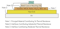
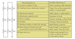
There are some guidelines designers should keep in mind when designing a cooling system and choosing the type of thermal interface. The first rule is not to forget the thermal circuit of Fig. 5. The tiniest chip could handle thousands of watts if it were not for the many thermal “resistors” between it and the external air. Knowing the techniques and associated cost and difficulty of reducing these “resistor” values is the key to success. (In Fig. 5, for an LED system, one might add an R7A and R7B for the added metal core PC board and its mounting interface material).
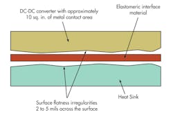
The second rule is to know which interface materials are most appropriate for a particular application. Fig. 6 shows a converter module/heat sink configuration that could typically represent 10 or more square inches of surface area. Depending on whether the heat sink surface is that of a stamped, extruded or precision-milled metal surface, each of the two mating surfaces might have undulations that vary 0.010-in. over the complete area, resulting in gaps as much as 0.020-in. Admittedly, this is a worst-case scenario, but it does happen.
Such air gaps could guarantee failure during overheating of the module. In such cases, a thick elastomer interface material, while not a particularly good thermal conductor (but operating better than air (but operating in the large diameter end of the “cone”) is still dramatically better than air (Table 1). There might be some reduction in module capability, but reasonable performance can still be obtained.
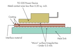
Employing an interface material under the TO-220 tab is another matter (Fig. 7). Here, the relative undulations, across an area well under one square inch, will be minimal. The “micro” surface irregularities begin to dominate, and we are in the small diameter of the cone. What are needed are the thinnest possible material and the maximum filling of the “micro voids.”
Other than soldering, little is better than the thermal grease or thin phase-change material and substantial pressure so that these materials can flow into the void and eliminate every cubic micron of air space. For this reason, a very thin, coated insulator is likely to be very effective as an insulator/heat conduction for a small area, and a thick, compliant elastomer material can be very effective if the heat can first be spread to a larger area.
Compressing the interface material (pad, grease, waxed aluminum, or 100% paraffin) ensures that it does the job for which it is intended: helping to fill in of any surface irregularities or flatness variations that could impede heat transfer. At higher power, even a thousandth of an inch of air space can dramatically affect maximum rating power capability.
Finally, mention should be made of other insulating materials historically found in military and some industrial applications. Aluminum oxide (Al2O3), beryllium oxide (BeO) and aluminum nitride are superior to plastic type materials but usually require a more sophisticated approach to assembly and therefore typically reflect additional cost. More recently a technology known as insulated metal substrate (IMS) has gained some popularity in dc-dc converters. The IMS approach involves a copper foil/polyimide (plastic/aluminum laminate to achieve electrical isolation and thermal conductivity. This process can have additional cost, manufacturing nuances and capacitance considerations, but if applied appropriately, it can provide excellent results. Regardless of the approach taken, the heat must travel from its source through many materials and interfaces as noted in Figs. 1, 2, and 5 and how that travel occurs must well understood.
Originally published in PCIM, November 1999, Ed Rodriguez has updated the article to include LED arrays.
References
1. “IEEE Transactions on Parts, Hybrids and Packaging,” June 1974.
2. Reference Data for Radio Engineers.” Howard Sams, 1977.
3. Modern Plastic Encyclopedia, McGraw Hill, 1993.
4. Electronic Engineering Master (IEEM) Hearst Business Publications, 1990.
5. Electronic Cooling Magazine, Flomerics Inc. May 1999.
6. Technical data sheets on materials from DuPont, Dow Corning, Castall Inc. and Cast Chem Inc.
