Eight-Switch Matrix IC Controls On/Off/Dimming and Diagnostics of LED Array
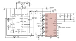
The LT3965 from Linear Technology is an LED bypass switching IC that contains a floating matrix of eight 17V/330m⦠NMOS switches. You can connect the eight switches in parallel and/or in series to bypass current around any one of LEDs in a string. When interfaced with an external constant current driver IC, the combination can control dimming and diagnostics for up to eight individual LEDs or LED segments. An I2C serial interface in the switch matrix provides the ability to control individual LEDs. Figure 1 shows the LT3965 with an external constant current LED driver (LT3955) and Table 1 lists the LT3965’s pin functions. You can independently program each of the eight channels to control each LED in the string in four different ways:
- Constant LED on
- Constant LED off
- LED Dimming without fade transition
- LED Dimming with fade transition
The LT3965 operates over the VDD input supply range of 2.7V to 5.5V and VIN range of 8V to 60V. A –40°C to 85°C junction temperature version, LT3965EFE, is housed in a 28-lead TSSOP thermally enhanced package that ensures a compact footprint for matrix dimming applications. An industrial temperature version, the LT3965IFE, guarantees operation from a –40°C to 125°C operating junction temperature range.
Typical applications include automotive matrix LED headlights, industrial lighting, and large LED display lighting. The I2C serial interface enables digital programming with 256:1 dimming ratios with or without the 11-bit resolution fade transition between the dimming states. Each switch can control and monitor a single LED or a segment of up to 16V of series-connected LEDs. The LT3965’s 8V to 60V input voltage range can accommodate a wide range of LED drivers commonly used in automotive and industrial applications.
I2C Serial Interface
The I2C serial interface is a two-wire open-drain interface supporting multiple slaves and masters on a single bus. Each device on the I2C bus is recognized by a unique address stored in the device and can only operate either as a transmitter or receiver, depending on the device’s function. A master is a device that initiates a data transfer on the bus and generates the clock signals to permit the transfer. Devices addressed by the master are considered slaves. The LT3965 can only be addressed as a slave. Once addressed, it can receive configuration data or transmit register contents. The serial clock line (SCL) is always an input to the LT3965 and the serial data line (SDA) is bidirectional. The LT3965 can only pull the serial data line (SDA) low and can never drive it high. SCL and SDA are required to be externally connected to the VDD supply through a pull-up resistor. When the data line is not being driven low, it is high. Data on the I2C bus can be transferred at rates up to 100kbits/s in the standard mode and up to 400kbits/s in the fast mode.
For larger LED matrix applications, up to 16 LT3965s can use a common I2C bus. By using multiple LT3965s the I2C serial interface enables communication between the master microcontroller and one or more LT3965s configured as slaves. The LT3965 provides an internal clock generator and also supports an external clock source for PWM dimming.
The LT3965 has nine command registers and two read-only fault status registers. The command registers are used to store the configuration bits sent by a master. The fault-status registers are used to store LED or overheat fault-status bits. Both the command registers and the fault status registers can be read by the master.
Fault Detection
Each channel has an LED fault detector you can program to detect an open LED fault at one of the four threshold levels: 4.5V, 9V, 13.5V, and 18V (default setting). When a channel detects an open LED, the channel switch turns on to bypass it, protecting the faulty LED string. With a proper LED reference voltage (<4V) applied to the LEDREF pin a single-LED shorted fault can still be detected, even when two, three, or four LEDs are being used per channel. When a shorted LED fault is detected in a channel, the channel switch will continue to operate normally, but a fault will be reported.
The LT3965 detects and reports open LED, shorted LED and overheat fault conditions via its ALERT pin and I2C serial interface. Once an open LED fault is triggered in a channel, the fault status bit matching the channel will be set in a status register, which will cause the ALERT pin to be asserted (pulled down) and the channel switch to be turned on to protect the switch. Once the IC triggers a shorted LED fault in a channel, the fault status bit matching the channel will be set in a status register, which will cause the ALERT pin to be asserted (pulled down). However, unlike the open LED fault, the channel switch will continue with what it is doing without switch protection.
The LT3965 triggers an overheat fault if the IC junction temperature exceeds 170°C. Once it triggers an overheat fault the LT3965 sets register status bits, causing the ALERT pin to be asserted (pulled down) and all eight channel switches to be turned on (LEDs turned off) to cool down the system.
EN/UVLO Shutdown
The EN/UVLO pin controls whether the LT3965 is enabled or in a shutdown state. The eight channel switches are off and the alert function is disabled in shutdown condition. A micropower 1.24V reference, a comparator and controllable current source, IS1, allow the user to accurately program the VIN supply voltage at which the IC will turn on and off. The falling value can be accurately set by an external resistor divider. When EN/UVLO is above 0.7V, and below the 1.24V threshold, the small pull-down current source, IS1, (typical 2.7μA) is active. The purpose of this current is to allow the user to program the rising hysteresis.
When the LT3965 is powered on or the EN/UVLO pin is toggled high, an internal power-on reset (POR) signal sets all registers to their default states. The eight channel switches are in off state (all channel LEDs are on) upon the POR. The POR also initializes each channel’s dimming counter with one-eighth dimming cycle shift, which can avoid simultaneous channel switching at the beginning of dimming cycle to reduce switching noises. When in dimming mode (with or without fade transition), the channel LED string always turns on at the beginning of its dimming cycle. When the channel LED string turns off, it remains that way until its next dimming cycle starts.
Dimming With/Without Fade Transition
You can independently program each channel of the LT3965 to perform dimming with or without fade transition. For dimming without fade transition, the dimming changes from the initial value to the target value in one dimming cycle. For dimming with fade transition, the dimming changes transitionally from the initial value to the target value step- by-step in multiple dimming cycles, following a predetermined logarithmic curve.
An ACMODE write command allows all eight channels to switch together. Also, you can switch all LEDs from on/off to off/on simultaneously using a single ACMODE write command. In addition, you can use an SCMODE write command to set both the addressed channel register bits to control the channel switch and the channel LED fault detecting thresholds.
Printed Circuit Board Layout
When laying out the printed circuit board, follow this checklist to ensure proper LT3965 operation:
1. Connect the exposed pad of the package directly to a large ground plane to minimize thermal and electrical impedance.
2. Keep the LED connection traces as short as possible.
3. Place power supply bypass capacitors as close as possible to the supply pins.
4. Place the RTCLK resistor as close as possible to the IC if a resistor is used to set LED dimming frequency.
About the Author

Sam Davis
Sam Davis was the editor-in-chief of Power Electronics Technology magazine and website that is now part of Electronic Design. He has 18 years experience in electronic engineering design and management, six years in public relations and 25 years as a trade press editor. He holds a BSEE from Case-Western Reserve University, and did graduate work at the same school and UCLA. Sam was the editor for PCIM, the predecessor to Power Electronics Technology, from 1984 to 2004. His engineering experience includes circuit and system design for Litton Systems, Bunker-Ramo, Rocketdyne, and Clevite Corporation.. Design tasks included analog circuits, display systems, power supplies, underwater ordnance systems, and test systems. He also served as a program manager for a Litton Systems Navy program.
Sam is the author of Computer Data Displays, a book published by Prentice-Hall in the U.S. and Japan in 1969. He is also a recipient of the Jesse Neal Award for trade press editorial excellence, and has one patent for naval ship construction that simplifies electronic system integration.
You can also check out his Power Electronics blog.


