Compute B/H Curve for Inductor with DC and Ripple Currents
Numerous variables and parameters are involved in building and specifying an inductor. Only a selected few give a designer limited degree of freedom. The rest, a majority, is utterly beyond the reach of users. For instance, among the latter, magnetic core flux density specification falls totally in the hand of core producers. Users have no choice but to accept what are offered and available. As a result, design iterations are often required to keep the part application within the constraints set by manufacturer.
Depending on the application, magnetic core flux may be attributed to driving voltage, current, or both. If not careful, all flux components may not be accounted for properly. The following graphs discuss a computational approach using a current-driven concept. Applying the technique of continuity of state, the total, steady state current of an inductor is derived. Given core geometry and material properties, flux density is computed and plotted against the actual data.
BOOST CONVERTER
A battery powered boost converter, shown in the simplified schematic (Fig. 1), is employed to power a TWT (traveling wave tube). Providing isolation and voltage step-up, the transformer operates in a 50% push-pull mode while the regulator loop works in PWM with duty cycle D. The core flux density of the boost choke needs to be evaluated to ensure no magnetic saturation.
It is also understood that the main power train alternates between two states, Fig. 2 and Fig. 3, when the PWM switch turns on, or off, with clock period T. Two state variables, the inductor current I and the output capacitor voltage V are involved. Along with that, two time constants, τL = L/rL and τC = RL×C, are identified.
SWITCH ON
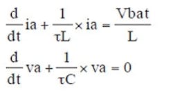
In switch-on state, with “a” suffix, two differential equations govern the circuit.
Assume a cyclical, yet unknown, starting conditions X1 = (Ia0, Va0)T a column vector, the solution in matrix form is given by:
Where:
Continue to next page
SWITCH OFF
In switch-off state, with “b” suffix, two equations in two variables are derived.
With starting conditions X2 = (Ib0, Vb0)T, also yet unknown, and taking the Laplace transform, the solution in transformed, and delayed form is given:
Taking the inverse Laplace transform, the solution in time-domain is given:
CONTINUITY OF STATES
At steady state, and at the point of switch-off, the following holds:
At the end point of switch-off time, the following is also true
Both equations establishing continuity of state transition at on/off boundaries enable us to solve X1 and X2. Once the cyclic starting conditions are obtained, the steady state inductor current and output voltage can be composed explicitly for one cycle.
where unit step function, u(t), is freely used to generate the appropriate gate function.
Continue to next page
CLOSED-LOOP DUTY CYCLE
In the above derivation, the switch duty cycle is still treated as an unknown parameter since it will change when either loading or input source varies. Given Fig. 1, the duty cycle, D, can be determined from:
Where:
K = Feedback ratio
Vref = Error amplifier reference
A = Amplifier gain
Fm = PWM gain (%/volt)
In general, the error voltage must exceed Vmin to begin PWM. It was accounted for above.
EXAMPLE: PLOTTING A CORE BH
The following core was selected for the inductor with N = 30 turns. The magnetic field intensity is given by H = Ni(t)/l and the flux density B = µoµrH. Fig. 4 shows the theoretical BH curve.
The theoretical flux density is compared against the actual core data (Fig. 5).
